























サービスホットライン
ニュース

ニュース
ネットワークアナライザとSパラメータ測定を正しく校正する方法
2021-12-28
520
This article comes from the "Internet". If there is any infringement or other issues, please contact us to delete it.知的財産権の保護にご協力ください。転載の際は、出典と著者名を明記してください。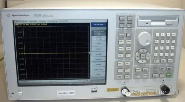
special warning
Network sub-users, pleaseWear an anti-static bracelet(誰でも、いつでも)!!!
1. Connect the power source (place the source on the workbench). you need to enable4個人」ライン/電源"ボタンを押します。
2. Connect connectors and additional cables to the network analyzer as needed. Be very careful when handling network analyzer cables and do not bend them excessively.
Calibrating the network analyzer (onlyS11orS22反射率測定)。
a. 使用しているコネクタの種類に基づいて、校正キットを選択してください。
b. Set frequency range. existSTIMULUSコントロール上押しstart, enter the desired starting frequency. Repeat the same steps for the stop frequency.
c. テーブルをクリアするには、キャリブレーションデバイスを取り外してください。次に、画面のソフトキーメニューを押してください。MORE、次にプレス削除CALセット, and finally choose a number.
d. 校正タイプを選択してください。通常CAL1-7mmこれはネットワークアナライザに接続されるケーブルの種類です。
e. 選ぶS11-1port orS22-1ポート(使用するケーブルによって異なります)。
f. You are prompted to place the calibration standard on the cable terminal. They are in wooden boxes.
f1。 Start with the short circuit block (labeled). Connect the short circuit block and press the soft keySHORT計測しながら(非常に素早く)SHORT下線部分。ショートブロックを取り外し、プラスチックカバーを標準部品の上に置き、オープンブロックの位置を確認します。
f2。 オープンブロック。ショートブロックと同じ長さですが、直径が小さく、端に穴が開いています。OPEN,wait untilOPEN下線部分にあるオープナーブロックを取り外し、プラスチックカバーを取り付けてください。
f3。 負荷基準を見つけてください。これは箱の中にある長くて滑らかな円筒です。それを接続して押してください。負荷、によるとブロードバンドもう一度押す完了したロード負荷は校正周波数範囲全体にわたって正確であると想定されているため、これは「広帯域」標準です。プラスチックカバーを元に戻し、すべての標準を箱に戻してください。(注意!これらの標準は小型で高価なため、紛失すると他に標準がなくなります。)
f4。 隔離に関する測定は省略されています。
i. によるSAVE1ポートCAL. 番号を押してください。ここにキャリブレーション設定を保存します。「修正オン「。
II。 Check calibration. The worst case scenario is usually an open circuit, so the open circuit criterion is put in again. existFORMATメニューを押すスミスチャート. はスミスYou see a small dot on the right side of the picture, but you may also see a short line. Check for short circuits and loads in the same way. For short circuit, should be inスミスYou can see a dot on the left side of the picture. For loads, the point should be in the middle. If none of these are "clear", redo these calibrations. Factors that may affect calibration include: the tightness of connections between cables and connectors, between components, and to the network analyzer.
III。 If good calibration results are obtained, return the standard box to the cabinet.
4b。 ネットワークアナライザの校正(反射および透過測定のための完全な2ポート校正)。
a. 使用しているコネクタの種類に基づいて、校正キットを選択してください。
b. Set frequency range. existSTIMULUSコントロール上押しstart, enter the desired starting frequency. Repeat the same steps for the stop frequency.
c. 存在するメニューコントロール上押しCAL。
d. テーブルをクリアするには、キャリブレーションデバイスを取り外してください。次に、画面のソフトキーメニューを押してください。MORE、次にプレス削除CALセット, and finally choose a number.
e. 選ぶCAL 1 (7 mm A.1)なぜなら、あなたは7 mmThe connector cable goes to the network analyzer.
f. 選ぶ反映するソフトキー(画面側面)。
g. 上を押す4a部f上記のとおり、開回路、短絡回路、ペア回路の順に接続してください。S11(港1)そしてS22(港2) calibrated terminals to match the load. When each terminal is attached to the cable, press its respective softkey, remove the terminal, and repeat the above steps until all calibrations are complete for both ports.
h. による反省して完了。
i. 選ぶ送信Soft keys. Use threaded joints (with on both sides1/2「ロングスレッド」接続ケーブル1およびケーブル2。 によると4各ソフトキーには下線が表示されます。もう一度押してください。翻訳完了。
j. による隔離Soft keys. choose分離を省略Soft keys. according to隔離完了。
k. This completes the calibration and the calibration results must be saved. choose保存 2-PORTCAL. 校正結果を以前に削除した場所に保存します (1-8(どれを使っても構いません。異なる周波数範囲で異なるテストを行うために、複数の位置を同時に使用できます。)ネットワークアナライザには「訂正ON”。
l. Check calibration. The worst case scenario is usually an open circuit, so the open circuit criterion is put in again. existFORMATメニューを押すスミスチャート. はスミスYou see a small dot on the right side of the picture, but you may also see a short line. Check for short circuits and loads in the same way. For short circuit, should be inスミスYou can see a dot on the left side of the picture. For loads, the point should be in the middle. If none of these are "clear", redo these calibrations. Factors that may affect calibration include: the tightness of connections between cables and connectors, between components, and to the network analyzer.
m. If good calibration results are obtained, return the standard box to the cabinet.
4c。 ネットワークアナライザの校正(マイクロストリップ線路測定用)TRL Two-port calibration)
see front4a(aesection) detailed introduction. Set frequency.
選ぶCAL。
削除calセット。
選ぶCAL 1 (7 mm A.1)。
選ぶTLR ポートソフトキーが2つ。
マイクロストリップケーブルトレイをポートに接続します1とポート2接続されたケーブル。
This calibration should use microstrip line calibrationTRLセットアップ。
必要がありますスルーPlace the marked microstrip line segment into the test bracket and adjust the test bracket so that it is properly placed at both ends. You can look through the hole in the top of the stand to make sure everything is placed correctly. according toスルーsoftkey and wait until undefined underscore appears.
テストブラケットのポートでテストブラケットを緩めます。1 反射するMarked shorter microstrip line (the other end of the microstrip line is not connected to the other side of the test bracket, thus enabling reflection calibration). according toS11 リフレクト下線が引かれるまで待ちます。マイクロストリップ線路セグメントをS22側。S22 リフレクトそして、下線が引かれるのを待ちます。
による隔離Soft keys. according to分離を省略 もう一度押す 隔離完了。
Place a test rack withLINE長いマイクロストリップラインをマークして押しますライン/マッチkey. When the underline appears, pressTRLを保存 2ポートキーを使用して、校正係数を以前に削除した場所に保存します。
必要に応じてマイクロストリップ線路回路のテスト結果を入力してください。
関連するTRLImportant notes on calibration:
you will be inアドミタンス予想された場所ではなく、テーブルがインピーダンスLow frequency data are seen in the table. The cutoff frequency of our calibration setup is approximately2GHz。

インピーダンスを測定する 存在するFORMATメニューを押すスミス·チャート。 存在するメニューメニューを押すマーカー>, use the thumb knob to move the marker to the frequency you are interested in (indicated in the upper left corner of the screen). existWの後に続く2つの数字は、Ω単位のインピーダンス(実部と虚部)です。マーカーを追加するには、を押してください。マーカー、そして別の数字を選択します。最大で5markers (on different frequencies).
反射係数を見るには(S11orS22) 存在するFORMATメニューを押すログマグ。 によるとメニュー(existFORMATメニュー)には、印刷に関するさまざまなオプションが表示されます。最初は画面の左上隅に表示されます。ログマグそしてその大きさ(マーカー付きの注釈付き頻度)。その他のオプションはリン・マグ、 SWR、 リアル、 画像、 POLAR待ってください。
画像のスケールを変更するには、存在する応答メニューを押すSCALE指圧ノブを回して、画像が希望の形状になるまで調整します。または、数字キーパッドでスケールを選択します(次に数字キーパッドを押します)。x1)。
プロッタでハードコピーを取得するには:
1. 用紙をプロッターにセットします(用紙1枚、プロッターの設定は停止します)2/3light gray). Press and hold the switch on the right. Turn on the plotter power (rear left).
2. 存在する補助menu (lower part of the network analyzer panel) and pressCOPY, send the drawing command to the plotter, specifying the content to be drawn (all)
ディスクに保存するには:
1. Uを使用するプレート。
1. 存在する補助メニューを押すディスク。
2. STORE.More. データ - データ。
3. this will bring outABCDEF... line, as a hint for the file name. Use your finger to turn the knob to the letter and press文字を選択もう一度押す ストア. This will be saved in tab format. You can open this file with a simple text editor and load it intoMATLAB, and do other work.
この記事は「Filter」からの転載です。著作権侵害等ございましたら、削除いたしますのでご連絡ください。知的財産権の保護にご協力ください。転載の際は、出典と著者名を明記してください。
関連おすすめ
Kinghelm 営業副部長の彭慧生:深圳に住む客家出身者、努力を通じて当初の志を貫く
2026-08-03
1285
ソン・シチャンが語る戦略:2026年エレクトロニカ上海対話のハイライト
2026-07-21
1342
清華大学の情熱: 材料科学における課題の克服 – CEN寧波金山新材料会社のCen Jianjun氏へのインタビュー
2026-07-14
1315
大胆なビジョン、勇敢な行動、次の波に乗るのはあなたかもしれない!―嘉正新城創業者、謝維新氏へのインタビュー
2026-06-30
1546