






















Service Hotline
News

News

Effect of image suppression filter on RF receiving front-end output noise
2021-12-28
929
The RF receiving front-end includes LNA, Filter, Mixer and other components. From the perspective of noise factor cascade, it is hoped that the first stage of the receiving link is a high-gain, low-noise-figure amplifier, in order to obtain a lower system noise figure and improve receiving sensitivity.In addition to the LNA, the receiving link also has a key component - the image suppression filter, which is located before the Mixer and is used to filter out image noise and image signals to improve the SNR and anti-image interference capabilities of the entire receiving link.
The following will describe in detail the impact of introducing an image suppression filter on the system noise floor through formula derivation.
1. There is an image suppression filter
Figure 1 shows a simplified RF front-end receiving chain, including LNA, Filter and Mixer. Assuming that the image suppression filter is ideal, that is, the insertion loss is 0dB and the out-of-band suppression is infinite, the image noise can be completely suppressed. Assume that room temperature is T0=290K, receiving link terminated with 50 Ohm load, GAand FAare the gain and noise factor of the LNA respectively, GMand FMare the gain and noise factor of Mixer respectively.
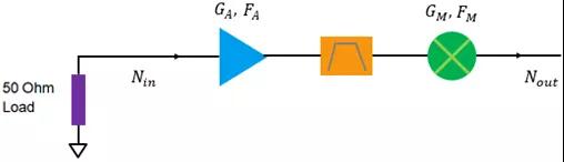
Figure 1. Simplified RF reception front-end: with image rejection filter
The input noise power of the receiving front-end is Nin=kBT0, the total output noise power is

(Formula 1)

(Formula 2)
From the perspective of system cascading, the noise factor and total gain of the entire receiving link are respectively
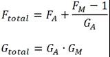
(Formula 3)
Because the current room temperature is 290K, the total output noise power at this time is

(式4)
Equations 2 and 4 are consistent. This is the calculation process of the noise floor of the entire receiving link when there is an image suppression filter.
2. No image suppression filter
Figure 2 shows a simplified RF receiving front-end without an image suppression filter. Due to the operating characteristics of the mixer, when the receiving link is working at this time, not only the noise in the expected operating frequency band will be converted to the intermediate frequency, but the noise in the image frequency band will also be converted to the intermediate frequency. This will cause the noise power output by the system to be doubled compared to when it contains an image suppression filter.
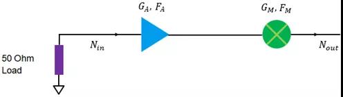
Figure 2. Simplified RF reception front-end: no image rejection filter
Assume that the Mixer’s frequency conversion loss in the image frequency band is , the gain and noise factor of the LNA in the image frequency band are respectively
 and
and . Only the simplest case is considered here, and the subsequent formula derivation and analysis will be based on the following assumptions:

(式5)
The total output noise power of the entire receive chain is

(式6)
Put equation 5 into the above equation to get

(Formula 7)
Further simplification of the above formula can be obtained

(式8)
From the perspective of system cascading, the noise factor and total gain of the entire receiving link are respectively
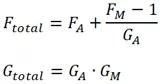
(式9)
It is worth mentioning that because there is no image suppression filter, for Mixer, the noise power fed into the previous stage LNA is twice that when there is an image suppression filter, so the above equation needs to be adjusted. It can be equivalent to the following structural block diagram with an image suppression filter.
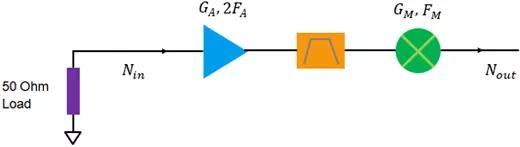
Figure 3. Equivalent structural block diagram with image suppression filter
The above figure equates the noise factor of the LNA to 2FA, the gain remains unchanged; the gain of the LNA can also be equivalent to 2GA, the noise factor remains unchanged. For simplicity, it is still assumed that the image rejection filter is ideal.
At this time, the total noise factor and gain of the entire receiving link are respectively
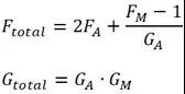
(式10)
Then the output noise power of the entire receiving link is

(式11)
Equation 11 and Equation 8 are consistent. If the gain of the LNA is equivalent to 2GA, the noise factor remains unchanged, then the total noise factor and gain of the entire receiving link are respectively
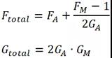
(式12)
Then the output noise power of the entire receiving link is

(Formula 13)
Equation 13 and Equation 8 are consistent. This is the calculation process of the noise floor of the entire receive chain when there is no image suppression filter.
in conclusion:Comparing the noise floor in the presence or absence of the image suppression filter, it can be seen from Equations 4 and 8 that if the gain of the LNA is very high, the noise floor without the image suppression filter is close to twice the noise floor in the presence of the image suppression filter. Comparing Equation 3 and Equation 10, we can see that when the gain of the LNA is very high, the total noise factor without the image suppression filter is close to 2 times the total noise factor with the image suppression filter.
This article is reproduced from "Microwave radio frequency network", supports the protection of intellectual property rights, please indicate the original source and author when reprinting. If there is any infringement, please contact us to delete it.
Related Recommendations