






















Service Hotline
News

News

A brief analysis of the error model and calibration of vector network analyzer
2021-12-28
910
Recently, I discussed the error model and calibration process of vector network analyzers with a colleague in the industry. I briefly compiled it and shared it with everyone. Welcome to discuss it together.
The error model of Yanet is indeed not easy to understand. Generally, only those who develop Yanet or specialize in testing technology will delve into it in depth. Before using Yanet to test, system error calibration is required. The purpose is to correct the error term introduced by the test device itself and obtain the true S parameters of the DUT.
System error calibration can be divided into single-port and dual-port system error calibration. The former is mainly used to test the reflection coefficient and its derived parameters of single-port devices, while the latter is mainly used to test the full S-parameters and its derived parameters of dual-port devices.
Single-port system error calibration includes OSM (open/short/match, sometimes called OSL - open/short/load) and normalized calibration. OSM calibration is a full single-port calibration, which can correct the error terms involved in comprehensive single-port testing, so it has the highest accuracy when testing single-port devices! Reflection normalization calibration is very fast, but using only a single calibration component of Open or Short can only solve for one error term of reflection tracking, so the accuracy is limited.
Figure 1 is an equivalent schematic diagram of a reflectometer. The reason why the reflection coefficient can be tested is that it contains a directional element - a directional coupler (most low-frequency vector networks use VSWR bridge), which achieves the separation of incident waves and reflected waves.
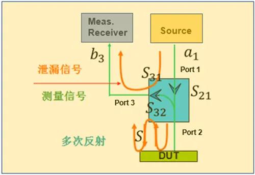
Figure 1. Brief schematic diagram of reflectometer
The basic process of the reflection test: the excitation source Source provides the signal a1, and most of the vector network ports are output to the DUT after passing through the coupler; the signal reflected by the DUT reaches the measurement receiver Meas. In addition, since the coupler is not ideal, its isolation is also limited, which causes part of the excitation signal a1 to be directly fed into the Meas.Receiver through the isolation channel of the coupler.
In other words, the signal b3 received by the Meas. Receiver actually contains three parts: the signal directly reflected by the DUT, the multiple reflection signal at the test reference surface, and the signal directly leaked through the coupler isolation channel.
Before listing the formulas, let’s briefly introduce the identification parameters in the figure: the coupler itself has 4 ports, but considering that the model only involves some parameters of the coupler, it is equivalent to a 3-port device here, and the ports are port1, port2, and port3. S21refers to the pass-through transmission coefficient of the coupler, S31refers to the transmission coefficient of the leakage channel, S32refers to the transmission coefficient of the coupling channel.
For the sake of simplicity, you can first draw the signal flow diagram above, as shown below: (ΓDUTis the real reflection coefficient of the DUT).
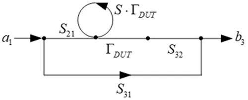
Figure 2. Signal flow diagram during single-port test
b can be obtained directly from the signal flow diagram3The expression of :

After simplification, the measured values of the reflection coefficient are as follows:
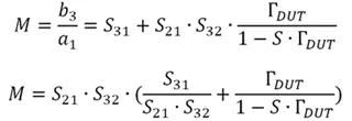
It can be seen from the above formula that the reflection coefficient measurement contains four error terms: S21,S32,S31,S. Generally called (S21· S32) 为反射跟踪R(eflective tracking),称S31/(S21· S32) is the directivity, abbreviated as D (directivity), and S is called the source port reflection coefficient.

After simplification, there are actually three error terms R, D, and S in single-port testing. During calibration, three standard parts, Open, Short and Match, are used respectively. Each standard part obtains an equation, which can uniquely solve the three error terms, and then correct the measurement results.
In order to facilitate the expansion to the case of two-port testing, an error two-port network is introduced, which is an equivalent two-port network containing four S parameters ei,j, the corresponding relationship with R, D, S is: R=e01· e10,D= e00/R,S= e11.
Each port of the vector network can obtain such an equivalent error two-port network. The errors involved in dual-port testing are much greater than those in single-port testing, so a more complex calibration method is required to correct the test results.
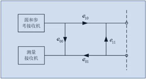
Figure 3. Equivalent error two-port network
The most classic two-port system error calibration is TOSM (Through, Open, Short, Match), sometimes also called SOLT (L, Load). TOSM calibration is suitable for a 12-term error model, and ultimately 10 errors are obtained after simplification. TOSM calibration can provide exactly 10 equations, so the solution to the error term can be uniquely determined.
The following takes the dual-port network forward test as an example to observe the possible signal paths: there are five possible signal paths from 1 to 5 in total. Among them, signal path 5 is the crosstalk of the port or test fixture. For simplicity, this term is not included in the following formula, that is, the ports are considered to be ideally isolated.
It can be seen from the signal flow diagram that the test forward transmission coefficient S21When , the error mainly comes from the transmission frequency response of the test device itself, multiple reflections from the test reference surface, etc. The error mapped to the two-port network is shown in Figure 5. Combined with the corresponding signal flow diagram in Figure 4, S can be derived21Expression between the measured value and the error term.
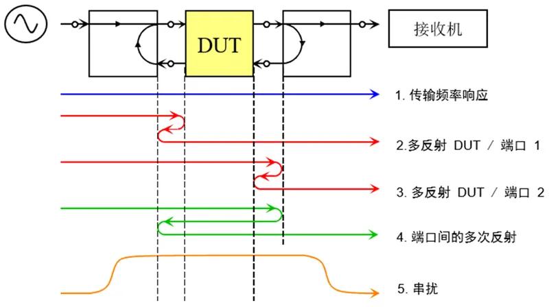
Figure 4. Two-port network: signal paths present during forward testing
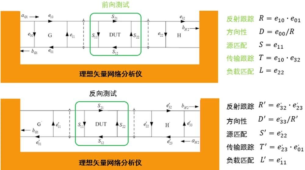
Figure 5. Signal paths and corresponding error terms during forward and reverse testing
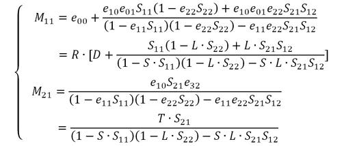
前向测试将会涉及到R、D、S、T(transmission tracking)、L(Load match)五项误差,S11 和S21The measured value expression of is as follows:
Backtesting will involve R’、D’、S’、T’、L’ (Load match) 五项误差,S12 和S22The measured value expression of is as follows:
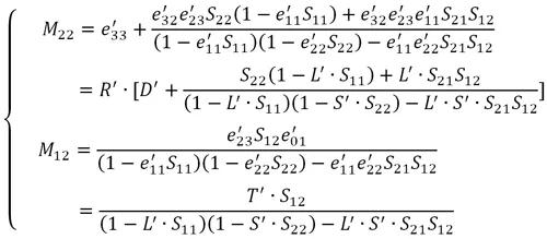
After TOSM calibration, these 10 errors can be obtained, and then substituted into the above equation to calculate the real four S parameters.
This article is reproduced from "Microwave radio frequency network", supports the protection of intellectual property rights, please indicate the original source and author when reprinting. If there is any infringement, please contact us to delete it.
Related Recommendations