






















Service Hotline
News

News

5G application layer throughput test configuration and implementation
2021-12-29
1356
Overview
3GPP has defined a new generation of 5G NR wireless communication technology starting from the R15 protocol. By introducing new air interfaces and new architectures, the bandwidth is larger and the spectrum efficiency is higher, thereby greatly improving the wireless communication experience rate and meeting the growing traffic demand of the mobile Internet. According to the definition of ITU International Telecommunication Union,Peak data rate is the maximum data achievable under ideal conditionsrate, which can be understood as the maximum capacity of the systemThe embodiment of loading capacity.For 5G eMBB scenarios, the peak downlink rate is up to 20 Gbps; the uplink peak rate is up to 10 Gbps.
In actual 5G link scenarios, there is often a certain gap between the application layer rate and the physical layer rate that are directly related to our experience. The configuration and parameter settings of the actual test environment will affect the application layer rate.As more and more manufacturers begin to pay attention to application layer throughput testing, Anritsu has launched a complete set of 5G NR application throughput measurement solutions for module manufacturers. This article will introduce to you the process of building and setting up the test environment.
Wiring diagram
As shown in the figure below, based on the physical layer measurement, the 5G NR analog base station (MT8000A) is expanded to an external server PC (supporting Linux system or Windows system) through optical fiber. The 5G module is expanded to the client PC through USB network sharing. Finally, the Iperf program is installed and run on the server PC and client PC to realize data filling and measurement of the application layer.
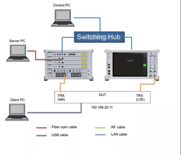
IP address of server PC: 192.168.20.200DUT IP address: 192.168.20.11 (MT8821C default client IP address 1)
IP address of the client PC: share the network connection via USB and get the same IP address as the DUT (192.168.20.11)After installing the optical network card on the external server PC, connect it to the optical fiber interface on the MT8000A through optical fiber to expand the NR server to the server PC (the detailed wiring is shown in the figure below).
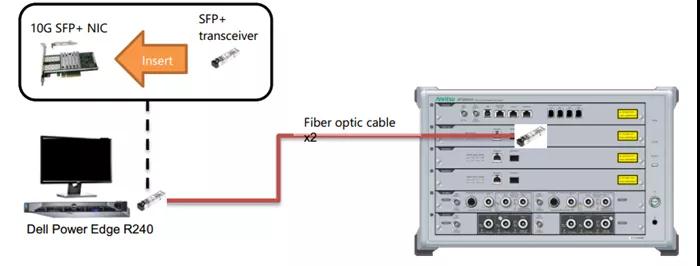
Detailed explanation of settings
The control software interface settings of MT8000A are as follows (the above picture shows the ipdata measurement mode settings, and the bottom picture shows the NR server IP address settings).
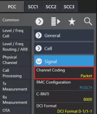
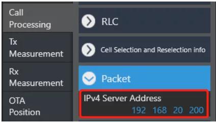
The server PC settings are as follows (the picture above shows the Windows system, the picture below shows the Linux system), and the subnet mask is set to 255.255.0.0 (the user can choose the setting according to the server's operating system type).
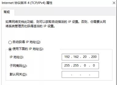
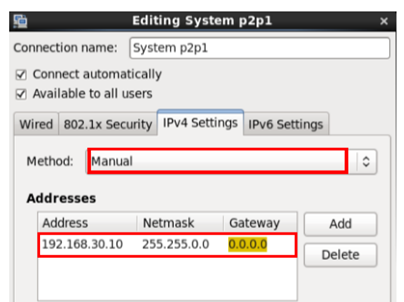
The settings of MT8821C are as follows (the upper picture shows the ipdata measurement mode settings, the lower picture shows the LTE server IP address and DUT allocation address settings), and the subnet mask is set to 255.255.0.0.
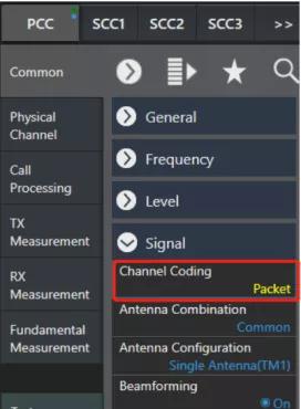
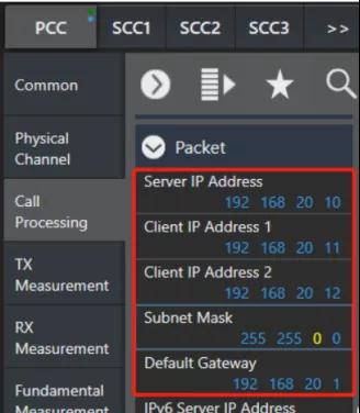
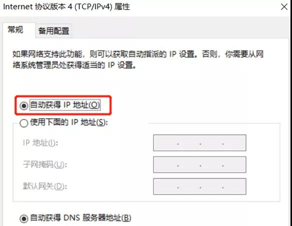
The IP address of the client PC is set as follows. With the APN, the specified IP address assigned by MT8821C can be automatically obtained.
Physical layer debugging
Continued from the previous article (Technical article | Influencing factors and implementation of 5G NR peak rate), taking the following frame structure as an example:
5ms 单周期:DDDDD DDSUU
D:GP:U(13:1:0)
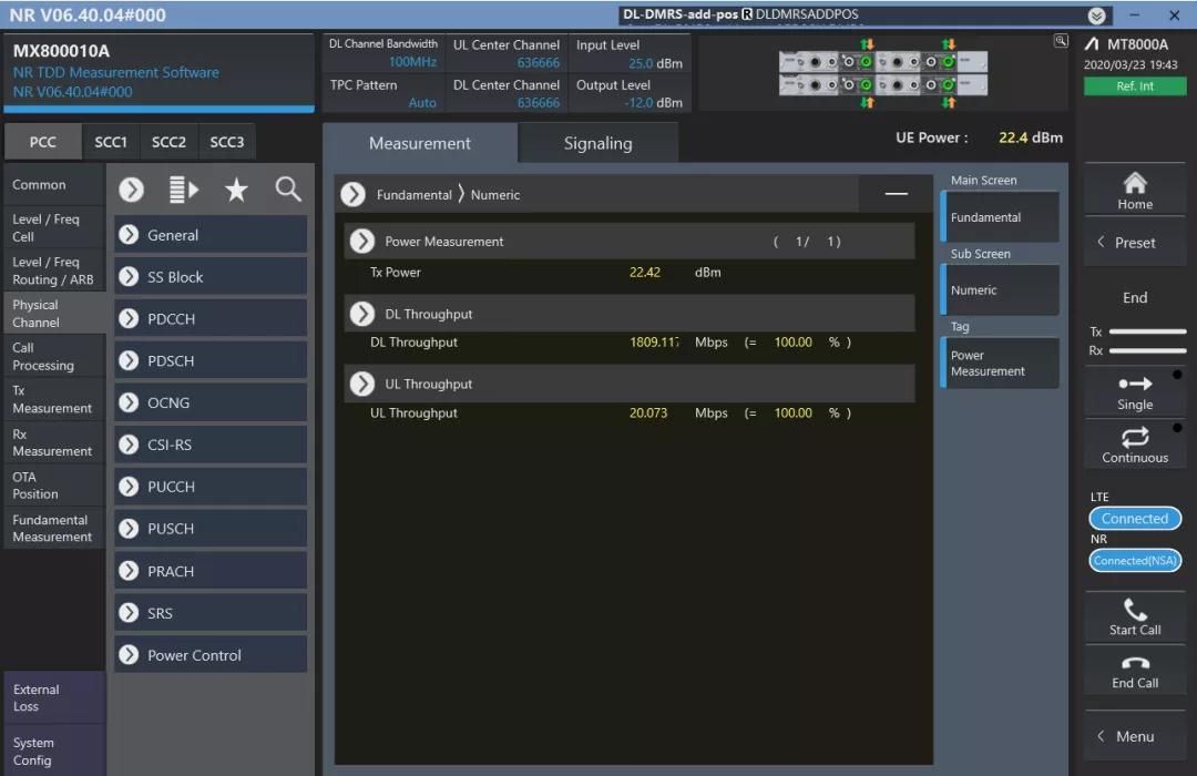
Under Sub-6GHz conditions, μ=1, 100MHz bandwidth, modulation method is 256QAM, airspace resource is 4x4MIMO, expansion coefficient is 0.8, downlink overhead is 0.14, the peak theoretical rate of 5G NR can be calculated to be 1.86 Gbps. As shown in the figure below, the measured 5G NR downlink physical layer throughput data of a certain module is: 1809.117 Mbps。
Add APN
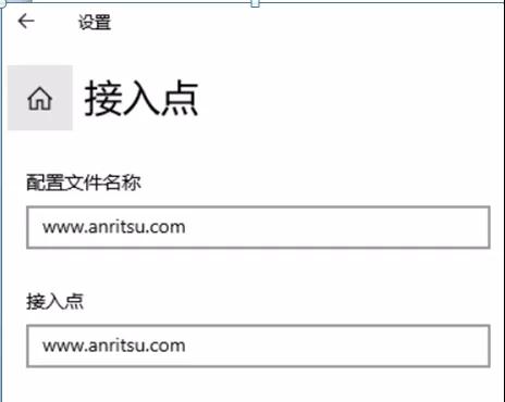
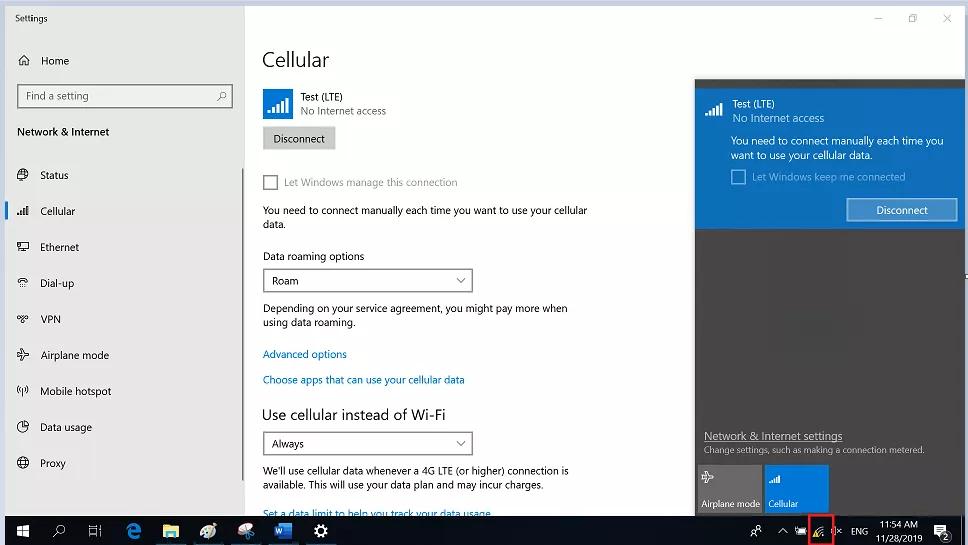
After adjusting the physical layer, share the DUT network to the client PC via USB, add APN and connect. The specific settings are as follows (afterwards, packet filling and measurement can be performed):"Network and Internet Settings" --> "Cellular" --> "Advanced Options" --> "Add Access Point" --> Enter www.anritsu.com in both the profile name and access point input boxes, and then save the settings.
Iperf filling and measuring
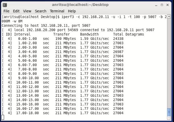
The client PC executes the following instructions to listen for packets:iperf3 -s -p 5007The server PC executes the following instructions to perform UDP packet injection:iperf3 -c 192.168.20.11 -u -i 1 -t 50 -p 5007 -b 2000M -w 8M
serverPCThe packet filling results are as follows (taking the Linux system as an example):
clientThe PC listening results are as follows:
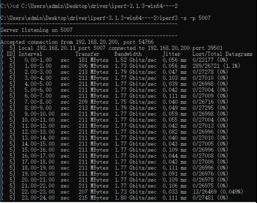
in conclusion:The physical layer throughput rate is 1809.117 Mbps, and the measured rate of the UDP application layer is 1.77G bps.
Actual measurement of application layer maximum throughput rate
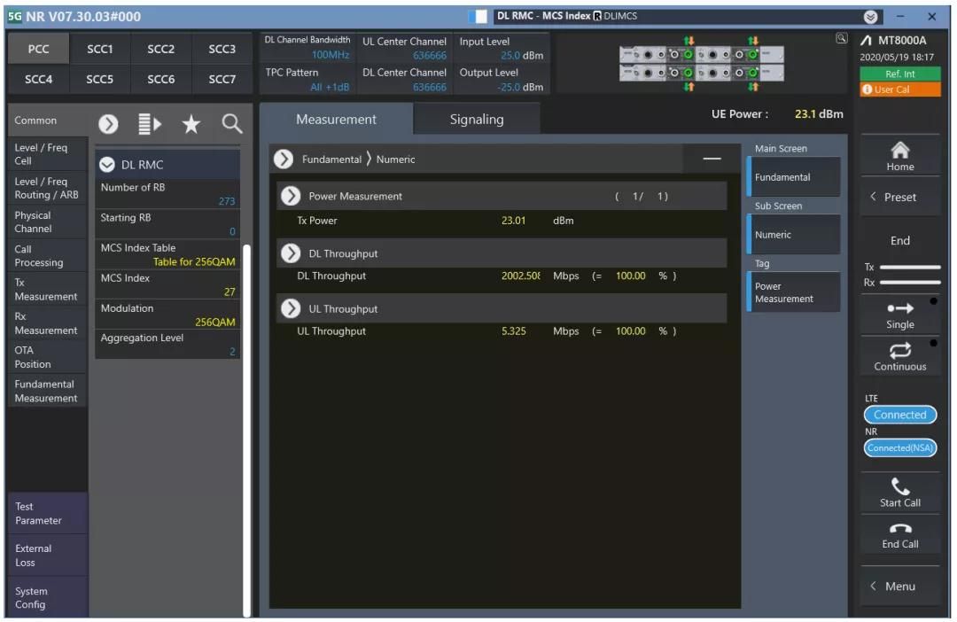
Continued from the previous article (Technical article | Influencing factors and implementation of 5G NR peak rate),Recently, a certain chip supports 95% duty cycle function, and the expected throughput value is 2.02 Gbps. Through joint debugging with the chip, the frame structure can be set to DDDDDDDDSU, where S(D:GP:U) is 11:1:2 (this frame structure is not specifically reflected in the expansion coefficient defined in 3GPP TS38.306). Under this frame structure, the maximum physical layer downlink throughput tested on Anritsu MT8000A is 2.002 Gbps, as shown in the following figure:
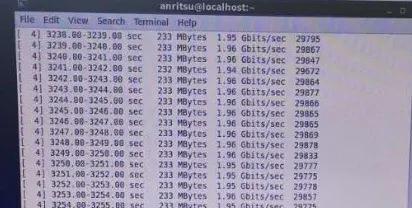
At this time, the measured rate of the UDP application layer is 1.95 Gbps.
This article is reprinted from "Anritsu", which supports the protection of intellectual property rights. Please indicate the original source and author when reprinting. If there is any infringement, please contact us to delete it.
Related Recommendations