






















Service Hotline
News

News
From paraboloid to phased array: a brief history of the development of airborne radar antennas
2021-12-28
914
As the needs of war change and science and technology advance, the "gold content" of air combat is getting higher and higher. The development of fighter aircraft airborne radar is a typical example. In terms of appearance, the most intuitive part of the "evolution" of radar equipment is the change in the antenna. Let’s briefly talk about the development of airborne radar antennas.
Airborne radar has evolved from simple air search and ranging functions in the early days to now not only taking into account search, tracking and fire control guidance in a large area, but also ground surveying and mapping, sar imaging and other multi-functions. Generally speaking, airborne radar requires antennas with characteristics such as high gain (to increase detection range), narrow beam (to increase angle measurement accuracy), and low side lobes (to resist interference). And achieve high gain, narrow beam. The simplest is to use directional antennas, such as Yagi antennas and parabolic (single reflector) antennas. The Yagi antenna is too large and the parabolic antenna is easier to achieve low side lobes than the Yagi antenna. Therefore, early airborne radars after the Cold War generally adopted the form of parabolic antennas.
Parabolic antenna (single reflector antenna).This kind of antenna uses a larger paraboloid as the main surface, and a horn at the center in front of the main surface as the feed source (forward feed) (the horn can also be deviated from the center position, which is called offset feed). Its working principle is quite similar to that of a parabolic mirror in optics. The working principle is that when the antenna works in the radiation mode, the spherical waves radiated by the horn hit the paraboloid, and the paraboloid transforms the spherical wave incident from the horn into a plane wave, causing it to radiate into free space. When working and receiving mode, the main reflecting surface converges the plane waves transmitted in free space, called spherical waves, and "returns" them to the feed speaker. This form of antenna is not difficult to process in the x-band and below, has a simple structure and is low in cost. However, the disadvantages are also obvious. Because usually parabolic antennas are easy to achieve high performance when the focal diameter ratio (the ratio of the distance from the horn to the reflecting surface to the size of the main reflecting surface) is high, the overall profile of the antenna is higher and the volume is larger. Especially when the antenna is rotated and scanned as a whole, it will occupy a lot of space in the machine head, so its scanning angle is also relatively limited. In order to solve these difficulties, a double reflective surface called "Cassegrain" form came into being.
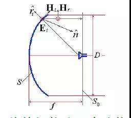
Basic composition and working diagram of parabolic antenna
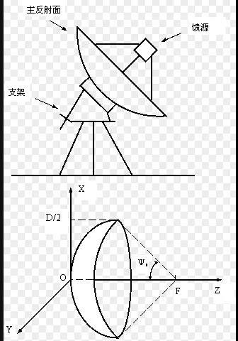
Basic composition and working diagram of parabolic antenna
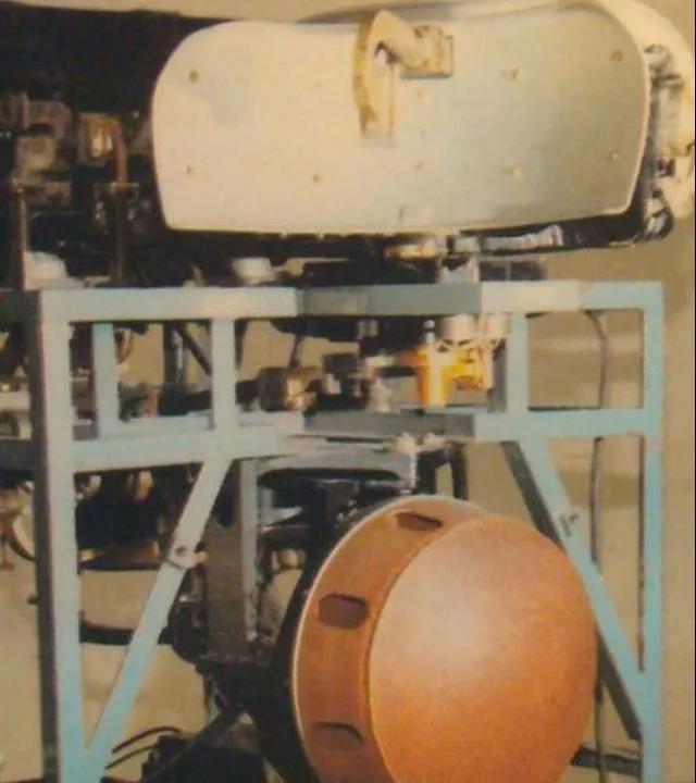
The antenna of the SL1 radar (imitation of the Soviet РП-1/5 type) equipped with the J-5A all-weather version
Cassegrain antenna.It is an antenna improved from the form of a single reflector antenna. Compared with a single reflector antenna, the added sub-reflector can initially optimize the electromagnetic waves emitted by the speaker and give it a more ideal distribution, reflecting it back to the main reflector. The main reflector then turns the shaped spherical wave into a plane wave and radiates it into free space. The advantage of this is that it can improve the efficiency of the antenna aperture, increase the gain, greatly reduce the focal diameter ratio, reduce the overall profile of the antenna, and reduce the size. After the receiver and feeder are also on the main surface, it is more conducive to system wiring layout and reduces system noise. However, the introduction of the sub-reflector will also bring about the problem of increased shielding of the main surface, which in turn will reduce the overall gain of the antenna and increase the side-lobe level.
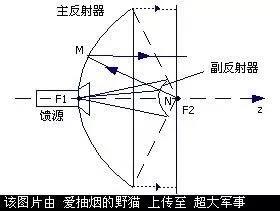
Basic composition and working principle of Cassegrain antenna
"Eagle" radar of the Su-15 interceptor aircraft (РП-11)
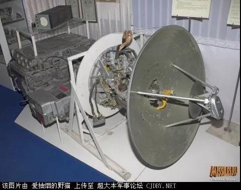
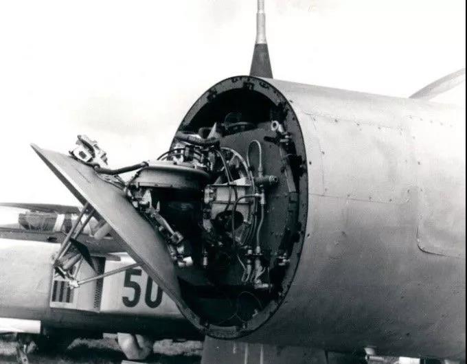
"Eagle" radar of the Su-15 interceptor aircraft (РП-11)
In order to solve the problem of subreflector occlusion, an antenna called an inverted Cassegrain antenna was proposed and widely used in airborne radar. Inverted Cassegrain, also known as deformed Cassegrain antenna. Based on the Cassegrain antenna, it changes the position of the sub-reflector into a polarized grid paraboloid and the position of the main surface into a polarized twisted plate. (In fact, in the inverted card antenna, the positions of the main and secondary surfaces are obviously different from those of ordinary Cassegrain antennas.) The working principle is quite different from that of Cassegrain antennas: the horn feed located at the polarization twisted version emits horizontally linearly polarized electromagnetic waves that are forward The polarization grid almost completely reflects back, and turns the spherical wave into a plane wave, which hits the polarization twisting plate at the back, "twisting" the horizontal polarization wave into a vertical linearly polarized electromagnetic wave, which is transmitted from the front polarization grid and radiated into free space. In short, although the beam emitted by the inverted card feed has been reflected twice, it is different from the ordinary Cassegrain antenna in that there is a polarization twisting process in the middle. The polarization grid located in front of the antenna only blocks horizontally polarized electromagnetic waves and has almost no effect on vertical linearly polarized waves. By the way, in order to combat ground clutter, airborne radar antennas are mostly vertical linearly polarized antennas. It achieves beam scanning by appropriately rotating the polarization twisting plate. Therefore, the flip-card antenna solves the problem of sub-reflector occlusion, and can also slightly offset the feed and polarization grid, further reducing the overall antenna profile. Because of its unique advantages, flip-up antennas are very popular in second-generation phones.
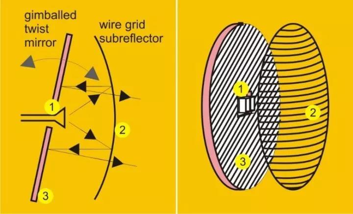
The working principle of the flip-card antenna is that the front horizontal bar is a polarization grid. The polarized twist plate is arranged at an angle of 45 degrees at the back.
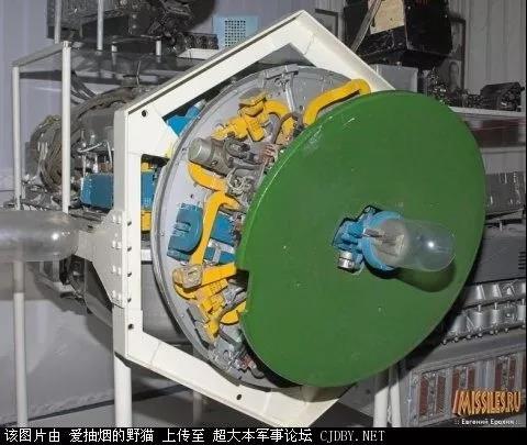
The inverted card antenna used by the Sapphire-21 radar equipped with the MiG-21BIS. Note that the polarization grid is not installed.
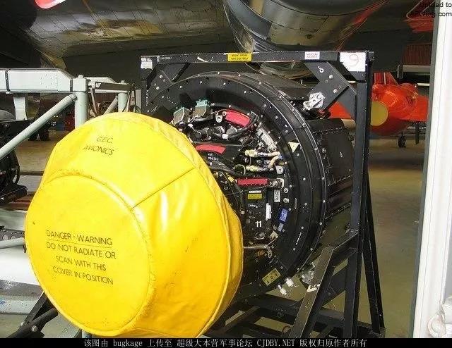
The inverted Cassegrain antenna used in the Tornado fighter AI-24 radar system
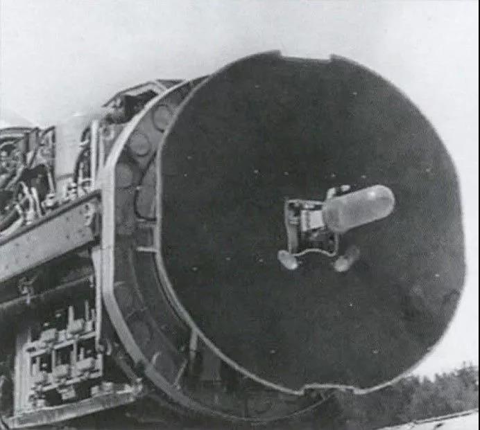
The inverted card antenna used by the Mig25 Tornado A radar has no polarization grid installed.

The inverted card antenna used by Su27's n001 radar is also noteworthy that its polarization grid surface is not installed.
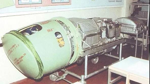
The inverted card antenna used by Su27's n001 radar. Note that this is in a complete state, with a polarization grid installed.
The basic working principles of the above-mentioned antennas are all based on the form of reflecting surfaces, which differ in details such as whether they are single reflecting surfaces or double reflecting surfaces, whether there is polarization twisting or not. By controlling the distance of the speaker from the main surface, adjusting the illumination taper, etc., it is easy to achieve high gain and low side lobes. Satisfactory performance can also be achieved in the early stages. Nevertheless, although the processing requirements for antennas that work in the form of reflective surfaces are not high (the X-band is relatively good, but the difficulty increases sharply in higher frequency bands), the cost is also acceptable. However, with the improvement of airborne radar performance, new requirements have also been put forward for the antenna part, such as larger scanning angle, lower side lobes and the realization of shaped beams. The inherent flaws in flip-card antennas include that there will always be energy leakage (which will cause a reduction in aperture efficiency and loss of gain), serious beam distortion during scanning (main lobe gain decreases, main beam widens, and side lobes rise), and there is always the problem of heavy antenna weight. Therefore, everyone thinks that the third-generation aircraft that want to seize air supremacy: mig29 and Su-27, both of them used inverted Cassegrain antennas in the early days, which seems somewhat shabby.
We know that in order to meet the requirements of airborne radar with high gain, narrow beam and low side lobes, parabolic antennas were used earlier because of their simple structure. There is also an antenna that is slightly more complex in form but has better performance, and that is the planar array antenna. Planar array antenna is a typical array antenna. From dozens to hundreds, or even thousands of small unit antennas, they are evenly arranged on the array surface according to certain rules and spacing. A single unit antenna may have a very wide beam and low gain, but relying on numerous unit antennas on the antenna array to work together, a very high gain, narrow beam, and even ultra-low side lobes can be achieved (it can even be upgraded to a planar phased array later). Therefore, due to its excellent performance, planar array antennas quickly replaced reflective surface antennas and became the mainstream in various third-generation, third-generation modified, and fourth-generation airborne radar systems. Today's advanced airborne radars, phased array radars, almost all use planar array antennas.
Common planar array antennas include waveguide (flat plate) slot array, open waveguide array, dipole array, Vivaldi antenna array, microstrip patch antenna array, etc.
The waveguide slot array is a common microwave transmission structure. Slits (slots) are opened on the surface of the waveguide, allowing the small slot to become an antenna to radiate electromagnetic waves. It has the advantage of matching the feed structure and has large power capacity. The airborne waveguide slots look like they are cut into a flat plate, so they are sometimes called flat slot arrays.
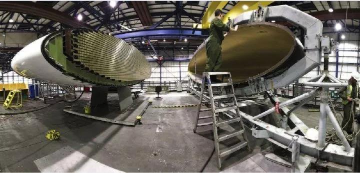
The APY1 radar used by E3 uses a waveguide slot antenna array
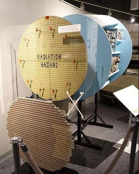
The flat-plate slot array used by the F15's APG63 radar has an IFF element antenna (array) protruding from the periphery.
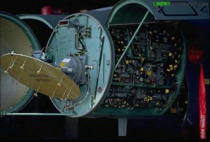
The flat-plate slot array used by the F15's APG63 radar has an IFF element antenna (array) protruding from the periphery.
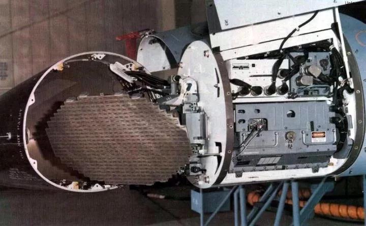
The flat-plate slot array used by the F16A/B's APG66 radar
Similar to this is the open waveguide array antenna. The open waveguide also uses a waveguide structure, but instead of slotting and slits, it directly uses the waveguide mouth surface to radiate electromagnetic waves. Because this type of open waveguide has a slightly larger cross-section and is overweight, it is more common in land-based or ship-based radars, and is rarely used in airborne radars.
The above structure that uses waveguides for feeding and radiation is conducive to antenna matching, and its large power capacity is its significant advantage. However, antenna bandwidth is often limited and weight is difficult to control. Subsequently, many novel designs were gradually used in airborne radar systems.
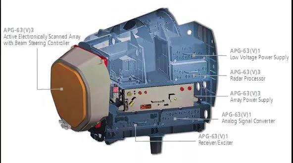
In fact, in the late Cold War, in order to achieve faster scanning speed and more powerful performance of airborne radar (such as simultaneous search, tracking, fire control, guidance, ground detection, etc.), engineers used phased array antennas for airborne radar, and it is still regarded as advanced technology. The appearance of a phased array antenna is not much different from a common planar array antenna. It can even be simply understood as a modification of the feed structure based on an ordinary machine-scanned planar array antenna (the back-end transmitter/receiver and signal processing algorithm will of course change a lot). By adding a phase shifter to the back end of the antenna unit, you can get a passive phased array antenna (PESA). If you don't like the phase shifter and adding a TR component, you can get an active phased array antenna (AESA). For antenna engineers, the same antenna array can be used for AESA or PESA. Therefore, planar array antennas have great potential to be upgraded to phased array antennas.
For radars upgraded to AESA antennas, they have greater transmit power, longer detection range, more sensitive beam scanning and more powerful beam shaping functions. It is also easier to obtain an average side lobe of -50 or -60dB.
Take the F22 as an example. The AESA radar of this new generation of stealth fighters likes to use dipole arrays (the picture shows the umbrella-shaped dipole array used by the F22's apg77 radar). The unit uses a dipole antenna, which has broadband characteristics. The unit pattern is wide and it is easy to achieve large-angle scanning.
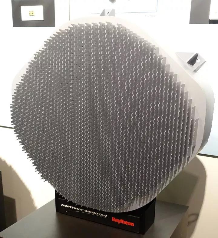
F22’s APG77 radar antenna
The one protruding at the front can easily be mistaken for a TR component. Strictly speaking, it is actually the surface of the antenna. The TR component is connected behind the antenna (although now the TR component is generally processed into one with the antenna, it is still discussed separately here)
The RBE2 AESA radar used in the new Rafale (as shown in the picture below) uses a Vivaldi antenna array. This kind of antenna unit is characterized by a particularly wide bandwidth, so the bandwidth of the entire antenna array can be expanded.
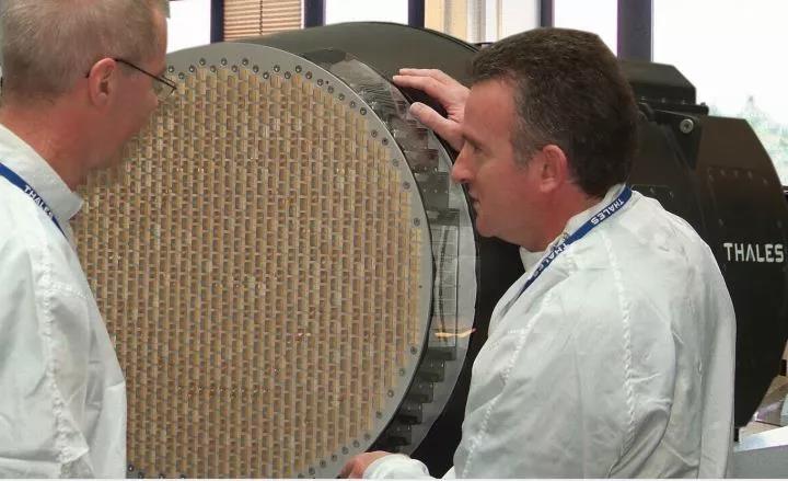
RBE2 AESA
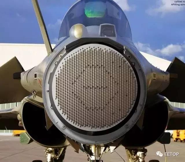
RBE2 AESA
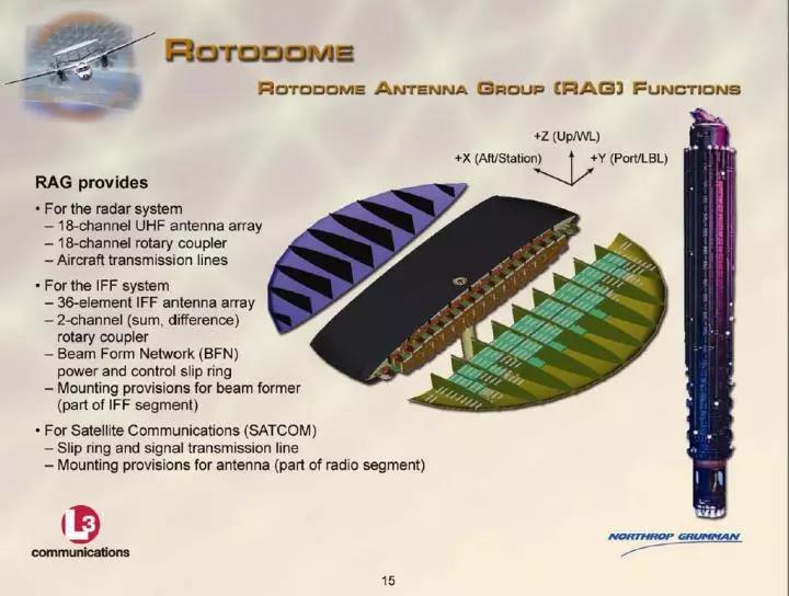
Of course there are some that are more special. For example, the APY9 radar used by the E2D early warning aircraft below uses a Yagi antenna as the unit. Because the wavelength of the electromagnetic wave in the uhf band it uses is long, its antenna size is very limited. In order to obtain a more ideal narrow beam and high gain, its antenna unit beam must be narrowed, so the Yagi antenna has become an ideal choice. As a unit, the high-gain Yagi antenna can significantly improve the gain of the array. But things are always relative. The narrow unit beam of the Yagi antenna greatly limits the wide-angle scanning capability of the array. When the antenna scanning angle deviates greatly from the normal, the gain decrease and the waveform distortion will be very obvious. Therefore, APY9 uses a combination of electromechanical scanning to make up for the shortcomings.
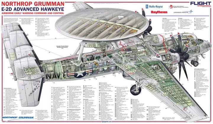
2*9 unit Yagi antenna line array used by E2D APY9 radar 2*9 unit Yagi antenna line array used by E2D APY9 radar
It is the development of phased array technology that has brought airborne antennas to a new stage.
The development of antennas is a microcosm of the overall technological development of radar. Although we cannot draw conclusions about radar performance or measure the overall performance of radar based on the appearance of the antenna, engineering often focuses on the coordination and balance between systems. If the overall performance of a radar system is advanced, the antenna cannot be inferior. In the future, engineers will continue to overcome problems such as large-angle scanning of phased array antennas (expanding the current scanning range of +60 degrees), ultra-wideband, common aperture, conformal, etc., to promote the development of airborne radar systems.
This article comes from the "Internet". If there is any infringement or other issues, please contact us to delete it.Support the protection of intellectual property rights, please indicate the original source and author when reprinting.
Related Recommendations