






















Service Hotline
News

News

Crimp Terminal Types: A Guide to Applications and Selection
2026-10-28
130
A crimp terminal is the metal contact that connects a wire to a connector system. It is not the plastic shell that holds it. That distinction sounds simple, but it causes a large share of wrong quotations, mismatched samples, and failed builds. A buyer may ask for a "crimp terminal" and receive a shell, a PCB header, or a complete cable assembly. None of those is the same part.
The confusion comes from using one phrase at different levels of a connection system: the metal contact, the plastic shell, and the complete mated system. This guide separates those levels, compares wire-to-wire and wire-to-board connections, and establishes a practical selection sequence. It does not cover standalone ring, spade, or quick-disconnect terminals.
What Is a Crimp Terminal?
A crimp terminal is a metal contact with a crimp barrel that is permanently deformed around a stripped wire. The conductor crimp compresses the wire strands and creates the electrical connection. The insulation crimp grips the wire insulation and provides strain relief. The mating end provides the electrical interface with the opposite contact.
Crimping is a controlled compression process: strip the wire, insert it into the terminal, crimp with the specified tool, and insert the terminal into the shell. Crimp height, crimp width, and tooling must match the terminal and wire. A crimped joint can look acceptable and still fail a pull test, a temperature-rise test, or a vibration test. Soldering is a different joining method and should not be used to compensate for a poor crimp.
Understanding the definition and crimping process leads to another question: which part in the connector system is actually being requested? In purchasing, the most common confusion is not how crimping works, but the difference between the metal contact, the plastic shell, and the complete mated system. These parts work together, yet they perform different functions and normally carry separate part numbers.
Their roles can be separated as follows:
- The crimp contact carries the signal or current and provides the mating end.
- The terminal shell positions and protects the contact and may provide keying, locking, and strain relief.
- The mating interface connects the shell to another wire shell or a PCB header.
The wire and crimp tool belong to the manufacturing process, not to the finished connector. In a catalog, the three roles above may appear under separate part numbers, which is why one request for a "crimp terminal" can produce quotations for different objects.
What Are the Different Types of Crimp Terminals?
Classification should start with the role a product performs, because each role has different dimensions, mating requirements, and failure modes. This is more useful than sorting products by the wording used on a catalog page.
Crimp Contacts
At the contact level, the decisive fields are the mating end, wire range, plating, and locking feature. Pin, socket, blade, and custom shapes all follow the same logic: the mating end fixes the interface, while the crimp barrel fixes the wire and tooling.
Contact material and plating affect resistance, mating cycles, and corrosion, so confirm them in the applicable specification. A locking lance, where present, is easy to overlook. If it is damaged, or if the contact is inserted into the wrong shell, the contact can back out under vibration or during mating.
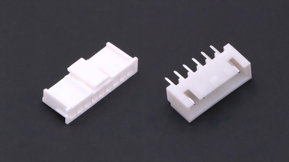
Do not assume that a product described as a terminal is a standalone crimp contact. PCB terminals, headers, and other board-mounted parts may use similar terminology while serving a different function. Confirm the mating end, termination method, wire range, and mounting style from the drawing rather than relying on the product name alone.
Crimp Terminal Shells
At the shell level, comparison moves from metal geometry to the mechanical family. Pitch is the center-to-center distance between adjacent contacts. Commonly used pitches include 1.25 mm, 2.0 mm, 2.5 mm, 2.54 mm, and 3.96 mm. These are different families, not interchangeable formats.
Pitch alone does not define compatibility. Two shells with the same pitch can have different contact cavities, keying, locking, and panel features. Position count and row layout also change the interface. These details determine whether the shell accepts the correct contact, prevents wrong mating, and provides the required strain relief.
A shell should therefore be selected as part of a qualified contact-and-shell system. The existence of a similar opening or the same pitch is not proof that another contact will lock, align, or perform correctly.
Wire-to-Wire and Wire-to-Board Crimp Connectors
At the system level, the question changes from "what holds the contact?" to "what does the shell mate with?" A wire-to-wire crimp connector joins two wire-mounted shells. It is common in inline cable connections, extensions, and harness-to-harness interfaces. Both sides have contacts and shells, and no PCB header is involved.
A wire-to-board crimp connector joins a wire-mounted shell to a PCB header. The cable side has the contact and shell. The board side has a header, also called a wafer. The header is a separate component that provides the board-side pins or sockets and must not be treated as the crimp terminal.
The choice affects mounting, mating direction, panel space, serviceability, and PCB layout. A wire-to-board design needs a board footprint that matches the header, not only a cable-side shell that matches the wire.
Published ratings require the same care. A rating for a contact, shell, or header does not automatically represent the complete mated system. As a first screening rule, the system is limited by its lowest-rated element, but the actual limit can also depend on temperature rise, energized contact count, wire gauge, and test conditions. Use the manufacturer's system-level rating or validate the complete assembly.
| Part or system | Role in the assembly | Typical application | Main selection factors |
|---|---|---|---|
| Crimp contact | Carries the signal or current and provides the mating interface | Inside a wire-mounted shell | Wire range, plating, mating end, locking lance, crimp tool |
| Crimp terminal shell | Positions contacts and provides the mechanical interface | Cable-side connector body | Pitch, positions, row layout, gender, keying, material, temperature |
| Wire-to-wire system | Joins two wire-mounted shells | Inline cable connections and harness extensions | Mating pair, keying, locking, wire range, strain relief |
| Wire-to-board system | Joins a cable shell to a PCB header | Board-to-cable connections inside equipment | Header series, pitch, mounting direction, board footprint, current rating |
| PCB header (wafer) | Provides the board-side mating interface | Soldered or mounted to the PCB | Pitch, pin count, straight or right-angle, current, voltage, temperature |
For a closer comparison of two common wire-to-board families, see Comparison of XH Connector and VH Connector. For the wider selection framework, see How to Choose the Right Wire-to-Board Connector for PCB.
The classification now answers what is being sold and what must mate with it. It does not yet answer whether a particular combination suits a specific wire, electrical load, and production process. Those questions require moving from product types to an evaluation sequence.
How to Choose the Right Crimp Terminal?
Selection follows the order in which the parts are assembled. The wire goes into the contact, the contact goes into the shell, the shell mates with another shell or a PCB header, and the crimp is formed with a tool. Following this order exposes a mismatch before it reaches the next step.
Wire Gauge and Conductor Type
The terminal's crimp barrel must match the wire range. Conductor size, strand count, and insulation diameter all matter. A fine-strand wire can be difficult to crimp with a tool designed for solid or coarse-strand wire. The strip length must match the crimp zone: too short, and the conductor crimp may miss strands; too long, and the wire may protrude into the mating area.
The insulation crimp requires its own check. Too loose, and it will not provide strain relief; too tight, and it can damage the wire. Wire selection is therefore complete only when the conductor, insulation, strip length, and crimp tool all fit the contact design.
Current and Voltage Ratings
Compare the operating duty with the exact contact, shell, header, and wire. A headline current or voltage figure is incomplete without its test conditions. Ambient temperature, energized contact count, wire gauge, spacing, and insulation all affect the acceptable operating limit.
Apply the required derating and use the manufacturer's system rating when available. If that rating is not published, validate the complete assembly. A component-level value should not be presented as proof that the mated system will meet the application.
Terminal and Shell Compatibility
Mechanical compatibility is where the three classification levels meet. The contact must fit the cavity in the shell and engage its locking feature. The shell must mate with the correct header or opposite shell. Pitch, positions, row layout, gender, keying, and locking all need to agree.
Use the manufacturer's mating chart or drawing rather than a visual match. A damaged locking lance, an incorrect cavity, or a shell from a similar-looking series can allow the contact to push out under load. The part may fit during assembly and still fail after vibration or repeated mating.
Installation and Operating Conditions
The final check is process compatibility. The crimp tool and applicator must be specified for the terminal and wire. For production, use qualified tooling and validated crimp settings. Inspect crimp height, crimp width, and pull strength, and verify insertion and withdrawal force against the applicable product specification.
A hand tool may be acceptable for prototypes, but not automatically for production. Vibration, moisture, chemicals, temperature, and mating cycles also belong in the review. A connector that works on a bench may not survive a moving vehicle, an outdoor enclosure, or a high-vibration machine.
These checks produce eight concrete answers:
| Checkpoint | Question to answer |
|---|---|
| Connection type | Is the interface wire-to-wire or wire-to-board? |
| Wire | What are the conductor size, strand type, insulation diameter, and strip length? |
| Electrical duty | What are the current, voltage, ambient temperature, and derating conditions? |
| Mechanical interface | What are the pitch, positions, row layout, gender, orientation, and locking method? |
| Compatibility | Are the contact, shell, header, and tooling from the same qualified series? |
| Environment | Are vibration, moisture, chemicals, and mating cycles within the product rating? |
| Production | Are the crimp tool, applicator, inspection method, and pull test defined? |
| Documentation | Are the applicable drawing, specification, and compliance documents available? |
These answers prepare the sample for approval. A missing or assumed answer leaves the interface unverified; it does not mean the risk is low.
Common Mistakes When Selecting Crimp Terminals
Most wrong-part orders happen when a required answer is absent and work continues anyway. The failure paths below show what can happen when one of the earlier checkpoints is skipped.
| Skipped check | Possible consequence | Required correction |
|---|---|---|
| Matching from a photo | The selected part may have different keying, locking, or cavity dimensions. | Compare the exact series, drawing, and mating chart. |
| Checking only the nominal wire size | The conductor crimp may be loose, or the insulation may be crushed or poorly supported. | Check conductor range, strand type, insulation diameter, strip length, and tooling. |
| Mixing similar product series | The parts may not lock or mate, or the contact interface may become unreliable. | Use a qualified contact, shell, and header family confirmed by the manufacturer. |
| Using a component rating as the system rating | The assembly may overheat because the contact, shell, or wire becomes the limiting element. | Validate the complete mated system and apply the required derating. |
| Approving only a visual crimp sample | The joint may fail a pull test, vibration test, or temperature-rise test after appearing acceptable. | Qualify the tooling and define crimp inspection, pull-test, and environmental criteria. |
A photo can help identify orientation or product shape. It cannot verify cavity, material, plating, wire range, tooling, or ratings. The contact, shell, header, wire, and crimp process must be approved as one system, and the interface must be rechecked whenever any part changes.
Conclusion
The quotation mismatch at the beginning is not simply a wording problem. It comes from starting with a loose category instead of identifying the function of the requested part. A crimp terminal is the metal contact, not the plastic shell. The contact carries the signal or current; the shell positions and protects it; the PCB header provides the board-side interface; the wire and crimp tool complete the manufacturing process.
Use that distinction to classify the product first, then select in assembly order: define the connection type, choose the series and pitch, verify the wire and electrical requirements, confirm contact, shell, and header compatibility, and validate the crimp process. This sequence prevents an unchecked interface from passing into a quotation or production release.
For exact specifications, compatible contact-and-shell combinations, drawing confirmation, or help reviewing a proposed assembly, contact Kinghelm's technical team. Send the intended wire, current and voltage conditions, mating direction, available space, and the proposed part drawings so the team can check the interfaces together.
Related Recommendations