






















Service Hotline
News

News

Absolutely full of useful information︱A summary of commonly used antennas and passive components
2021-12-29
1144
1. Antenna principle
1.1 Definition of antenna:A device that can effectively radiate electromagnetic waves to a specific direction in space or can effectively receive electromagnetic waves from a specific direction in space.
1.2 Antenna functions:Energy conversion - conversion of guided waves and free space waves;Ø Directional radiation (reception) - has a certain directionality.
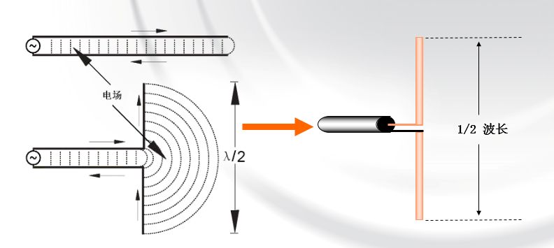
1.3 Antenna radiation principle
1.4 Antenna parameters
uradiation parameters
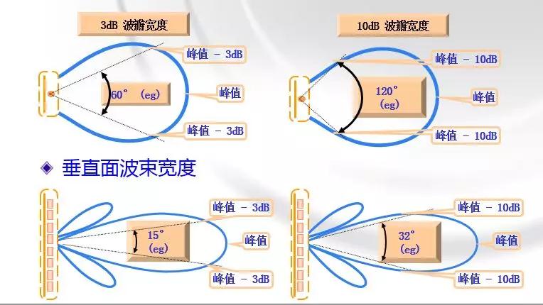
ØHalf-power beamwidth, front-to-back ratio;
ØPolarization method, cross-polarization discrimination rate;
ØDirectivity coefficient, antenna gain;
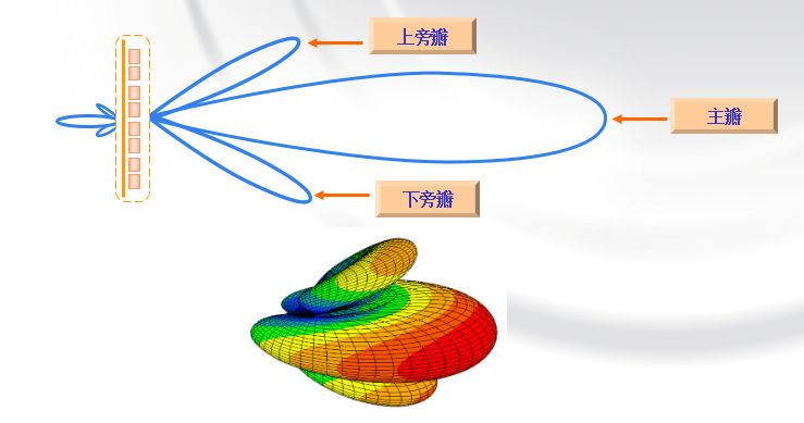
ØMain lobe, side lobe, side lobe suppression, zero point filling, beam downtilt...
uCircuit parameters
ØVoltage standing wave ratio VSWR, reflection coefficient Γ, return loss RL;
ØInput impedance Zin, transmission loss TL;
ØIsolation Iso;
ØPassive third-order intermodulation PIM3…uAntenna side lobes
uHorizontal beam width
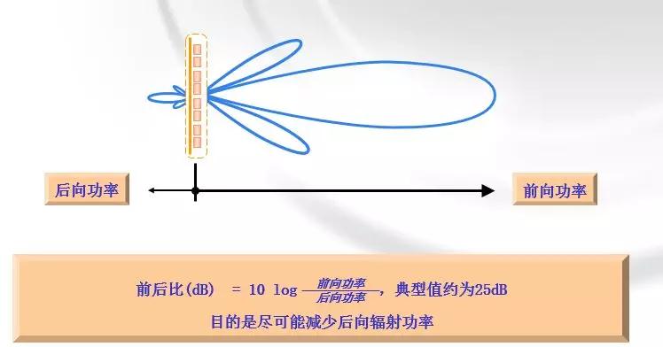
u Front-to-back ratio: The ratio of the forward radiated power of the specified directional antenna to the backward ±30°radiated power
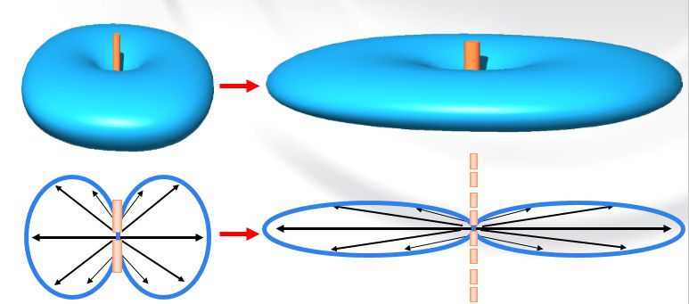
The relationship between u gain, antenna size and beam widthFlatten the "tire", the more concentrated the signal, the higher the gain, the larger the antenna size, and the narrower the beamwidth;
Several key points of uantenna gain:
ØAntenna is a passive device and cannot generate energy.
Antenna gain is simply the ability to effectively concentrate energy to radiate or receive electromagnetic waves in a specific direction.
ØThe gain of the antenna is generated by the superposition of the oscillators.
The higher the gain, the longer the antenna length.
The gain increases by 3dB and the volume doubles.
ØThe higher the antenna gain, the better the directivity, the more concentrated the energy, and the narrower the lobe.
1.5 Radiation parameters
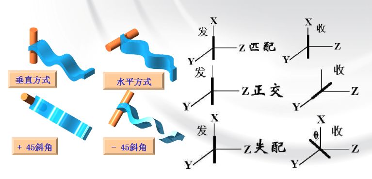
uPolarization: refers to the trajectory or changing state of the electric field vector in space.
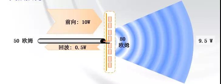
1.6 Circuit parametersuReturn loss
In this example, the return loss is 10log(10/0.5) = 13dB
VSWR (Standing Wave Ratio) is another measure of this phenomenon
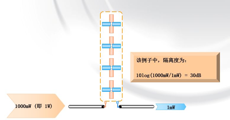
uIsolation: It is the proportion of a polarization signal received by another polarization signal
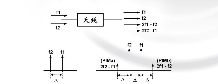
u Passive intermodulation (PIM):When two frequencies f1 and f2 are input to the antenna, due to nonlinear effects, the signals radiated by the antenna include other frequencies, such as 2f1-f2 and 2f2-f1 (3rd order), in addition to frequencies f1 and f2.
2. Antenna products
2.1 Antenna naming method
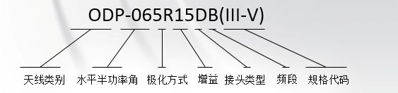
Antenna category:
ODP (outdoor directional plate antenna), OOA (outdoor omnidirectional antenna), LCD (indoor ceiling antenna), OCS (outdoor bidirectional antenna), OCA (outdoor cluster antenna), OYI (outdoor Yagi antenna), ORA (outdoor dish antenna), IWH (indoor wall-mounted antenna), etc.
Half power angle:032,065,090,105,360 (base station antenna)020, 030, 040, 050, 060, 075, 090, 120, 160, 360 (repeater antenna)
Polarization method:R (dual polarization), V (unipolarization)
Gain:According to actual indicators, the current maximum is 21dbi
Connector type:D (Din head), N (N-type head), S (SMA head), T (TNC head), etc.
Frequency band:Specification code:The Roman letters indicate which generation of product. The following letters and numbers indicate the ESC downturn angle, shaping, ESC and other information. F shaping; V ESC; RV remote ESC
2.2 Base station antenna
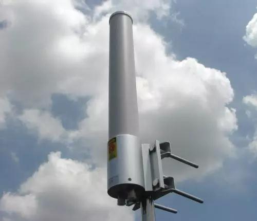
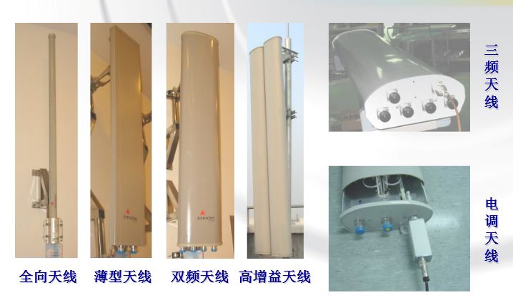
omnidirectional antenna
Dual band antenna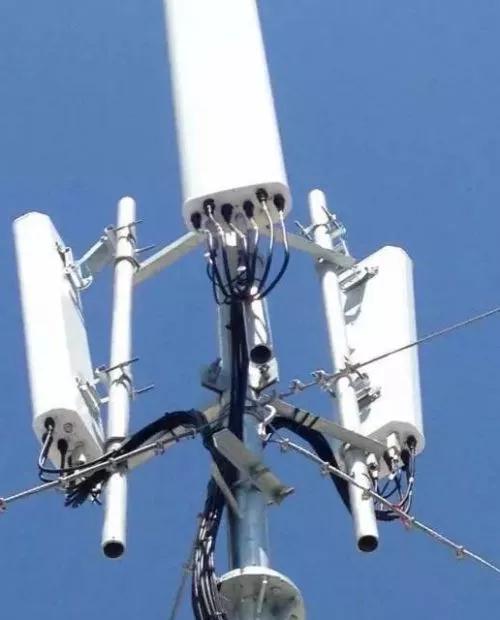
Tri-band antenna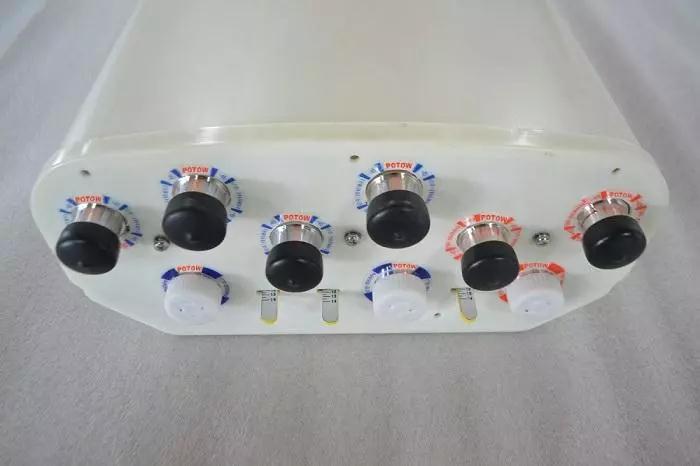
2.3 Distributed system antenna
Smoke detector type ceiling antenna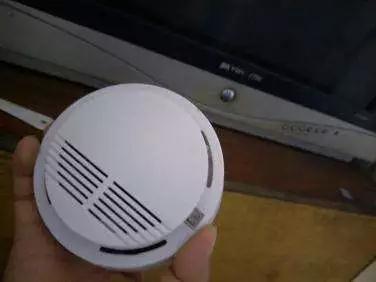
Lamp type ceiling antenna
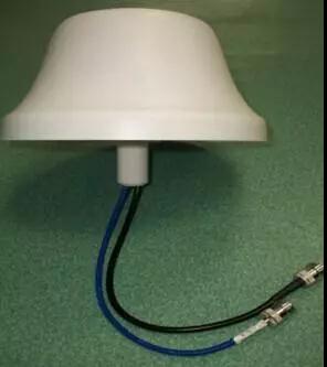
wall mounted antenna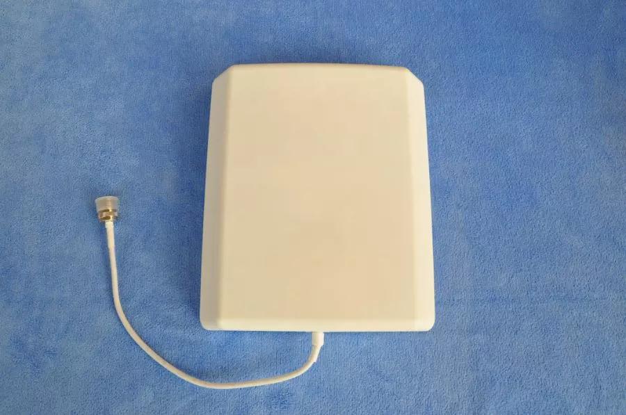
Donor Antenna:ØNarrow beam, strong directivity ØHigh front-to-back ratio
Yagi antenna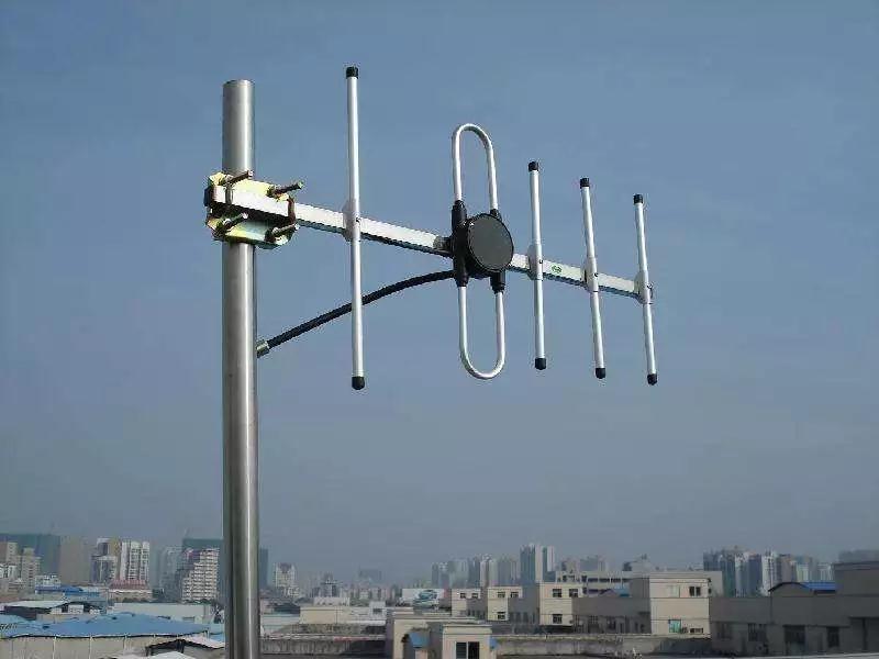
corner reflector antenna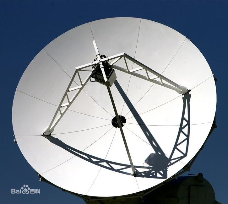
parabolic antenna
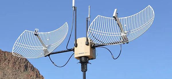
User antenna

3. Overview of Passive Components3.1 Overview of microwave passive components
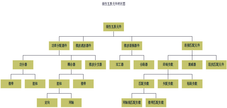
ØPassive devices are divided into linear devices and nonlinear devices.
ØLinear passive components are divided into reciprocal and non-reciprocal.
ØLinear reciprocity components only linearly transform microwave signals without changing the frequency characteristics, and satisfy the reciprocity principle.
Usually what we call passive components refers to linear reciprocal components.
3.2 Linear reciprocal component tree diagram
3.3 Power splitter
ØA power splitter is a device that divides the energy of one output signal into two or more outputs.
Essentially an impedance transformer.
ØIs it possible to reversely use a power divider to replace a combiner?
ØWhen used as a synthesizer, it not only requires high isolation and low standing wave ratio, but also focuses on the requirement to withstand high power.
Considering that the output ports of commonly used cavity power dividers are mismatched and have large standing waves; microstrip power dividers can withstand low power in reverse, we do not recommend using power dividers in reverse to replace combiners.
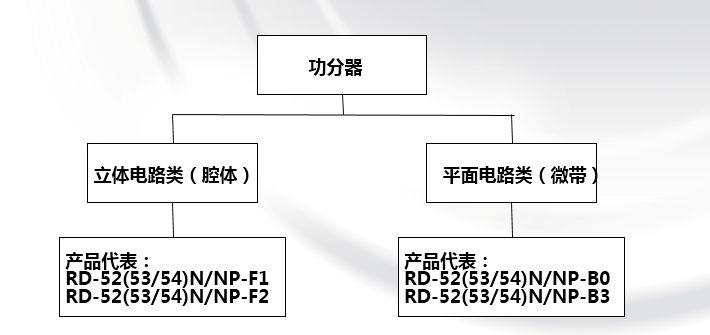
3.4 Classification of power dividers
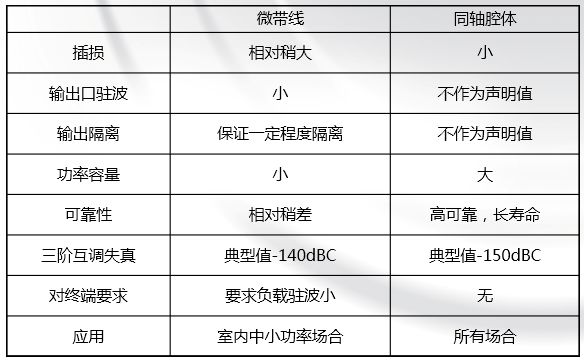
3.5 Comparison of power divider classifications
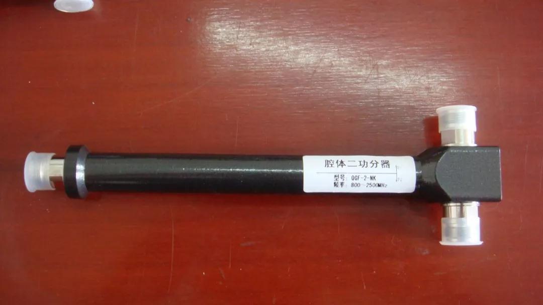
3.6 Characteristics of cavity power splitter
ØCavity power splitter uses high-quality alloy as conductor, and the filling medium is air;
Ø It can withstand relatively large power, up to 200W; while the dielectric loss and conductor loss are basically negligible, and the insertion loss is small, which can be less than 0.1dB.
ØHowever, since there is no isolation resistor, the output port isolation is very small, so the cavity power divider cannot be used as a power combiner.
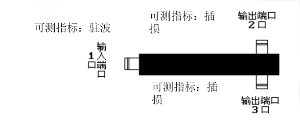
3.7 Schematic diagram of power splitter test indicators
As shown in the figure, the standing wave ratio can be measured at port 1; the insertion loss can be measured at ports 2 and 3. However, due to the device characteristics of the cavity power splitter itself, the standing wave at the output port and the isolation of the output port are not proposed as declared values.
4. Introduction to couplers4.1 Coupler
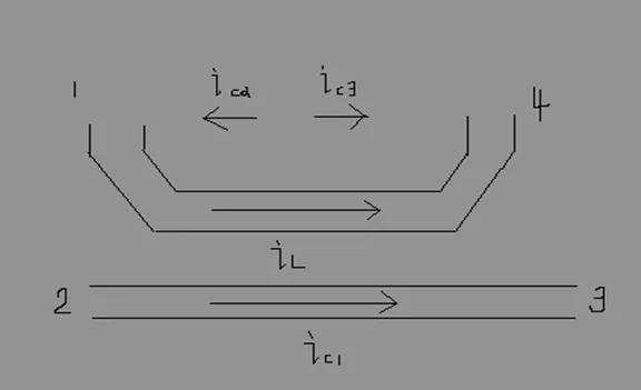
ØA coupler is a component that distributes a part of the energy of the input signal through electric field and magnetic field coupling to become the coupling end output, and the remaining part becomes the output end output to complete power distribution.
Ø The power distribution of the coupler is unequal.
Also called power sampler.
4.2 Principle diagram of four-port network coupler
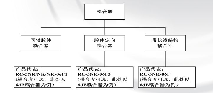
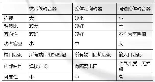
4.3 Coupler classification
4.4 Directional coupler
Ø Directional couplers are commonly used to sample microwave signals in specified flow directions. The main purpose is to separate and isolate signals, or conversely mix different signals. When there is no internal load, directional couplers are often a four-port network.
Ø Directional couplers are often implemented in two ways:

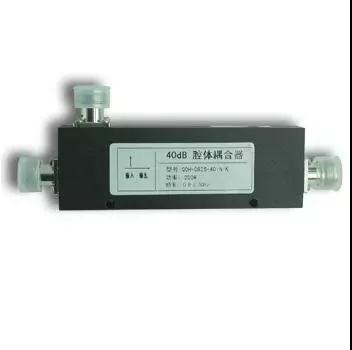
4.5 Cavity Coupler
Features:Carrying high power and showing low loss.
reason:
1. The filling medium inside the cavity is air. During the transmission process, the medium dissipation caused by the air medium is much lower.2. The coupling line strip is generally made of conductors with good conductivity (such as silver-plated copper surface), and the conductor loss is basically negligible.3. The cavity is large in size and dissipates heat quickly. It can withstand high power.
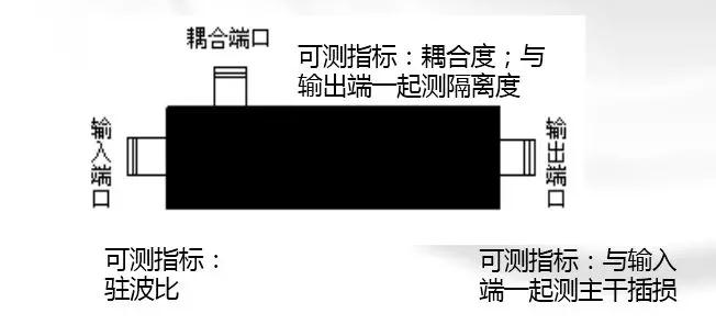
4.6 Schematic diagram of coupler index test
As shown in the figure, where directivity = isolation - coupling, data cannot be read directly.
5. Introduction to 3dB bridge
5.13dB bridge
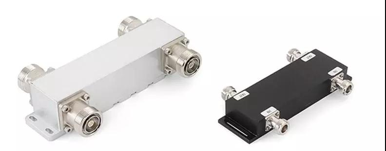
The 3dB bridge coupler is a type of directional coupler.When used as a power combiner, the two input signals are connected to mutually isolated ports, and the coupled output and straight-through output ports are reciprocal. If used as two outputs, regardless of loss, the sum of the input signal power is divided into the two output ports.When used as a single-port output, the other output must be connected to a matching power load to absorb the output power of the port. Otherwise, the system transmission characteristics will be seriously affected. At the same time, it will also bring an additional 3dB loss, which will have an impact on the cost and reliability of the active part of the system application.
5.2 Main engineering applications
Mainly used in combining applications between different carriers in the same frequency band.
Due to the discrete nature of the circuit and processing assembly, the isolation of the input port of the bridge coupler is relatively low, and it is not recommended to be used in combining applications between different frequency bands.
In summary, when applying multi-frequency combining, except that adjacent carrier frequencies in the same frequency band (such as adjacent carrier frequencies in the GSM downlink band) can only use 3dB bridges and are not suitable for duplex/multiplex combiners, it is recommended to give priority to duplex/multiplex combiners in order to improve system performance indicators and increase reliability.
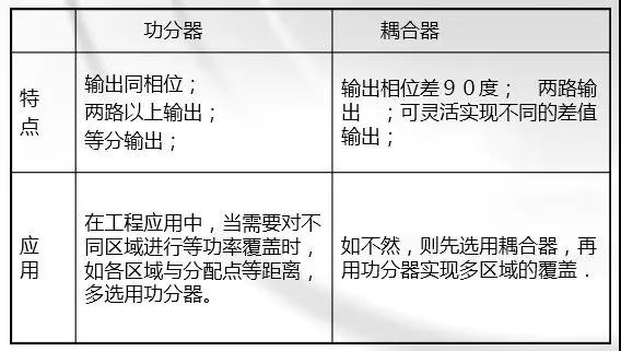
5.3 Power splitter VS coupler
6. Introduction to combiner6.1 Combiner
ØFunction:
Combine multiple signals into one signal output
ØCategory:
Classification according to actual combined frequency bands
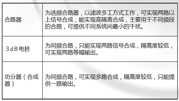
6.2 Combiner VS bridge VS power divider
7. Introduction to attenuator7.1 Attenuator
ØThe attenuator is a two-port reciprocal component
ØThe most commonly used attenuator is the absorptive attenuator.
ØCoaxial attenuators are usually used in engineering, consisting of "π" or "T" type attenuation networks.
ØCoaxial attenuators usually have two types: fixed and variable attenuation.
ØAttenuators are mainly used in detection systems to control microwave signal transmission energy and consume excess energy, thus extending the dynamic range of signal measurement, such as power meters, spectrum analyzers, amplifiers, receivers, etc.
This article is reproduced from " ittbank", support the protection of intellectual property rights, please indicate the original source and author when reprinting. If there is any infringement, please contact us to delete it.
Related Recommendations