






















Service Hotline
News

News
4G and 5G base station antenna engineering knowledge and application scenarios
2021-12-28
941
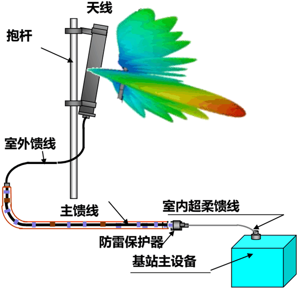
1 Base station antenna overview
This chapter introduces the classification of base station antennas and the appearance of different types of antennas in mobile communications.
1.1 Base station antenna classification
Omnidirectional antenna:In the horizontal pattern, it appears as 360° uniform radiation, which is commonly known as non-directional. In the vertical pattern, it appears as a beam with a certain width. Generally, the smaller the beam width, the greater the gain. Omni-directional antennas are generally used in mobile communication systems in suburban and county-based station types, with large coverage areas.
Directional antenna:In the horizontal pattern, it appears as radiation within a certain angle range, which is commonly known as directivity. In the vertical pattern, it appears as a beam with a certain width. Like an omnidirectional antenna, the smaller the beam width, the greater the gain. Directional antennas are generally used in urban cell-based stations in mobile communication systems, with small coverage, high user density, and high frequency utilization.
Different types of base stations are established according to the requirements of the network, and different types of base stations can choose different types of antennas according to needs. The selection is based on the above technical parameters. For example, an omnidirectional station uses an omnidirectional antenna with basically the same gain in each horizontal direction, while a directional station uses a directional antenna with significant changes in gain in the horizontal direction. Generally, antennas with a horizontal beam width of 65° are selected in urban areas. Antennas with a horizontal beam width of 65°, 90°, or 120° can be selected in suburban areas (depending on the station configuration and local geographical environment). In rural areas, it is most economical to choose an omnidirectional antenna that can achieve wide-area coverage.
Mechanical antenna:Refers to a mobile antenna that uses mechanical adjustment of the downtilt angle. After the mechanical antenna is installed vertically to the ground, if network optimization is required, it is necessary to adjust the position of the bracket on the back of the antenna and change the inclination of the antenna. During the adjustment process, although the coverage distance in the main lobe direction of the antenna changes significantly, the amplitudes of the vertical and horizontal components of the antenna remain unchanged, so the antenna pattern is easily deformed.
Practice proves:The optimal downtilt angle of the mechanical antenna is 1°-5°; when the downtilt angle changes between 5°-10°, its antenna pattern is slightly deformed but not much; when the downtilt angle changes between 10°-15°, its antenna pattern changes greatly; when the mechanical antenna changes After tilting down 15°, the shape of the antenna pattern changes greatly, from a pear shape without tilting to a spindle shape. At this time, although the coverage distance in the main lobe direction is significantly shortened, the entire antenna pattern is not within the sector of the base station. The base station's signal will also be received in the sectors of adjacent base stations, causing serious intra-system interference. In addition, during daily maintenance, if you want to adjust the downtilt angle of the mechanical antenna, the entire system must be shut down, and monitoring cannot be performed while adjusting the antenna inclination. Adjusting the downtilt angle of the mechanical antenna is very troublesome, and maintenance personnel generally need to climb to the place where the antenna is placed to make adjustments. The downtilt angle of the mechanical antenna is a theoretical value calculated through computer simulation analysis software, and there is a certain deviation from the actual best downtilt angle. The number of steps for adjusting the tilt angle of the mechanical antenna is 1°, and the third-order intermodulation index is -120dBc.
Electronically adjustable antenna:Refers to a mobile antenna that uses electronic adjustment of its downtilt angle. The principle of electronic downtilt is to tilt the vertical pattern of the antenna downward by changing the phase of the collinear array antenna oscillator, changing the amplitude of the vertical component and horizontal component, and changing the field strength of the composite component. Since the field strength in all directions of the antenna increases and decreases at the same time, it is ensured that the antenna pattern changes little after changing the tilt angle, shortening the coverage distance in the main lobe direction, and at the same time reducing the coverage area of the entire pattern within the serving cell sector without causing interference. Practice has proven that when the downtilt angle of an electrically adjustable antenna changes from 1° to 5°, its antenna pattern is roughly the same as that of a mechanical antenna; when the downtilt angle changes from 5° to 10°, its antenna pattern is slightly improved compared to that of a mechanical antenna; when the downtilt angle changes from 10° to 15°, its antenna pattern is better than that of a mechanical antenna. The change is larger; when the mechanical antenna is tilted down 15°, its antenna pattern is significantly different from that of the mechanical antenna. At this time, the shape of the antenna pattern does not change much, the main lobe direction coverage distance is significantly shortened, and the entire antenna pattern is within the base station sector. Increasing the downtilt angle can reduce the sector coverage area without causing interference. Therefore, using an electrically adjustable antenna can reduce call loss and reduce interference. In addition, the electronically adjustable antenna allows the system to adjust the lower tilt angle of the vertical directivity pattern without shutting down, and monitor the effect of the adjustment in real time. The step accuracy of adjusting the tilt angle is also high (0.1°), so the network can be finely adjusted; the third-order intermodulation index of the electrically adjustable antenna is -150dBc, which is 30dBc different from the mechanical antenna, which is beneficial to eliminating adjacent-channel interference and spurious interference.
Dual polarized antenna:Dual polarization antenna is a new type of antenna technology that combines two antennas with orthogonal polarization directions of +45° and -45° and works in the transmit and receive duplex mode at the same time. Therefore, its most prominent advantage is that it saves the antenna of a single directional base station. Quantity; Generally, the directional base station (three sectors) of the LTE digital mobile communication network uses 9 antennas, and each sector uses 3 antennas (space diversity, one transmitting and two receiving). If dual-polarized antennas are used, each sector only requires 1 antenna; at the same time, due to the dual Among polarized antennas, the polarization orthogonality of ±45° can ensure that the isolation between the +45° and -45° antennas meets the intermodulation requirements for isolation between antennas (≥30dB), so the dual The spatial distance between polarized antennas only needs 20-30cm; in addition, dual-polarized antennas have the advantages of electrically adjustable antennas. Using dual-polarized antennas in mobile communication networks, like electrically adjustable antennas, can reduce call loss, reduce interference, and improve the service quality of the entire network. If a dual-polarized antenna is used, since the dual-polarized antenna does not have high requirements for erection and installation, there is no need to acquire land to build a tower. You only need to erect an iron column with a diameter of 20cm, and fix the dual-polarized antenna on the iron column according to the corresponding coverage direction. This saves infrastructure investment, makes the base station layout more reasonable, and makes the selection of the base station site easier.
For the selection of antennas, mobile antennas that suit the needs of mobile networks in the region should be selected based on actual conditions such as network coverage, business volume, interference, and network service quality:
· In high-traffic areas with dense base stations, dual-polarized antennas and electrically adjustable antennas should be used as much as possible;
· Traditional mechanical antennas can be used in areas such as borders and suburbs where the traffic volume is not high, base stations are not densely populated, and coverage is only required.
1.2 Internal structure and types of mobile communication base station antennas
1.2.1 Directional Plate Element Array Antenna
Plate directional antenna is the most commonly used type of extremely important base station antenna. The advantages of this kind of antenna are: high gain, good sector pattern, small back lobe, easy control of vertical pattern depression angle, reliable sealing performance and long service life. The appearance of the antenna is shown in the figure below:
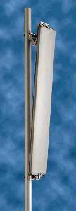
Figure 1-1 Schematic diagram of the appearance of a plate directional antenna
1.2.1.1 Formation of high gain of plate antenna
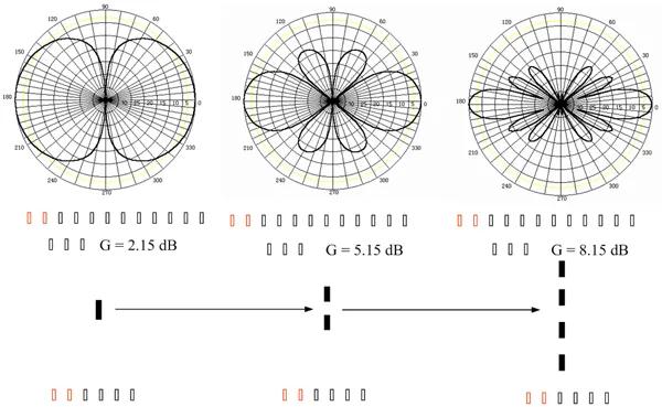
Figure 1-2 Use multiple half-wave oscillators to form a vertical linear array
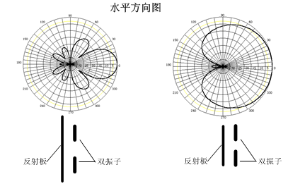
Figure 1-3 The principle of adding a reflective plate to one side of the linear array to achieve horizontal orientation (taking the vertical array of two-half-wave oscillators with a reflective plate as an example)
At present, the base station directional antenna designs of antenna manufacturers basically all adopt plate-type oscillator array structures. There are two types of oscillators selected, as described in the following two sections.
1.2.1.2 Symmetric oscillator
Standard half-wave symmetrical array (add an additional oscillator to reduce the height of the oscillator from the ground and reduce the thickness of the antenna)
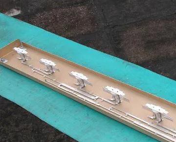
Figure 1-4 Directional plate antenna synthesized by multiple half-wave oscillators
1.2.1.3 Microstrip oscillator
The deformation of the half-wave oscillator uses the principle of 1/4 wavelength transmission line to form radiation:
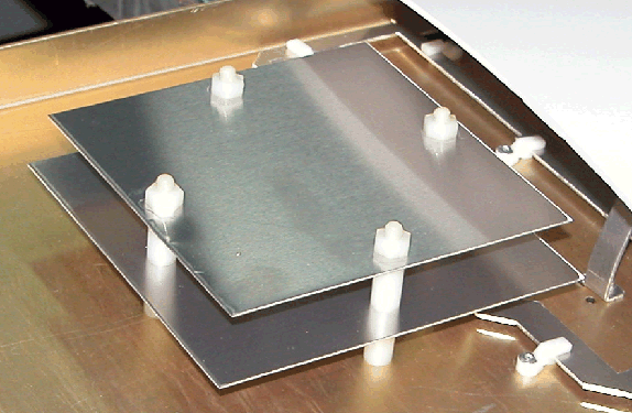
Figure 1-5 Directional plate antenna synthesized by multiple microstrip oscillators
1.2.2 Omnidirectional series-fed dipole antenna
The omnidirectional antenna uses multiple half-wave oscillators to achieve the synthesis and enhancement of radiation gain.
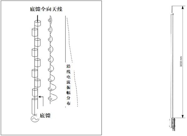
Figure 1-7 Series-fed oscillator structure and product form of omnidirectional antenna
2 4G LTEAntenna Types and Comparative Analysis
The main content of this section is to introduce the comparative analysis of coverage and traffic between LTE dual-polarized antennas and single-polarized antennas.
2.1 Correlation analysis between LTE dual-polarized antenna and single-polarized antenna
The introduction of LTE multi-antenna technology adds a spatial dimension of freedom to wireless resources and puts forward new requirements for wireless channel models. The Spatial Channel Model (SCM) is proposed in 3GPP TR 25.996. This model is suitable for systems with a bandwidth of 5 MHz and a carrier frequency of about 2 GHz. The maximum number of multipaths is 6. The LTE system requires that the wireless channel can support up to 20 MHz. Therefore, the SCME (SCM Extension) model is used in technical report 36.803 to extend the channel bandwidth to 20 MHz and support the maximum number of multipaths to 9. Among them, the wireless transmission characteristics between eNB and UE are a time-varying function, which changes with changes in antenna configuration, antenna direction angle, antenna correlation, and scattering environment, as shown in the figure below.
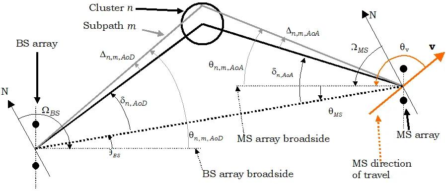
Figure 2-1 Schematic diagram of SCM angle parameters
The difference in wireless performance between dual-polarized antennas and single-polarized antennas (antenna spacing 10λ) mainly depends on the correlation coefficient of the base station antenna. When the correlation coefficient is 0, it indicates that the antennas are relatively independent and the correlation is low. When the correlation coefficient is 1, it indicates that there is strong correlation between antennas. When the system uses transmit diversity mode (such as SFBC), receive diversity and MIMO dual-stream mode, the wireless performance of low-correlation antennas is better than the performance of high-correlation antennas. The figure below is the SFBC performance simulation results with correlation coefficients of 0.25, 0.5, 0.6 and 1 respectively. From the simulation results, when the correlation coefficient is 0.25, its performance is basically unaffected (compared to a correlation coefficient of 0). The performance of SFBC with correlation coefficients of 0.5 and 0.6 drops by about 0.3dB to 0.4dB.
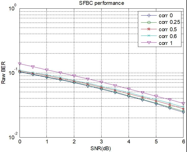
Figure 2-2 Comparison of SFBC link-level performance with different correlation coefficients
China Mobile tested the correlation coefficients of different antenna configurations in July 2008. The specific correlation coefficients are shown in the table below:
Table 2-1 Correlation coefficients corresponding to different antenna configurations
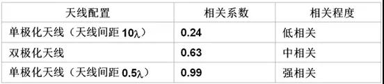
Note: The correlation coefficients in the above table were obtained by China Mobile based on SCME model testing in dense urban areas. In dense urban areas, this correlation coefficient is somewhat representative. However, it does not mean that this correlation coefficient can be mapped to a specific project, nor does it mean that this correlation coefficient is applicable to all models of dense urban areas.
2.2 Performance comparison between LTE dual-polarized antenna and single-polarized antenna
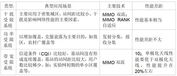
LTE defines seven multi-antenna transmission modes, including transmit diversity, precoding-based MIMO, beam forming, etc. The seven transmission modes defined by LTE are mainly to consider the flexible selection of transmission modes under different scenarios and different channel models. Usually the bottlenecks and shortcomings of wireless mobile communication network performance are divided into the following three categories:
Power constrained systems:
Typical application scenarios: The main purpose is to increase coverage and overcome fading, such as effective areas, wide coverage in rural areas, etc.
Type of antenna technology used: transmit diversity, receive diversity
Performance gap: The performance improvement of the 10λ single-polarized antenna is less than 5% compared to the dual-polarized antenna, and the performance gap between the two is not big.
Interference limited systems:
Typical application scenarios: Mainly used in dense urban areas where the distance between stations is relatively small. Interference is a major factor affecting network performance.
Antenna technology type adopted: RANK=2 MIMO dual stream, RANK=1 MIMO single stream, RANK adaptive
Performance gap: The RANK adaptive algorithm is significantly better than the MIMO forced dual-stream; at the same time, the performance of dual-polarized antennas is basically the same as that of 10λ single-polarized antennas.
Bandwidth constrained systems:
Typical application scenarios: The channel conditions (CQI) are relatively good, there is no continuous coverage between base stations, the distance between base stations is relatively large, and the number of users is relatively sparse. For example: single cell coverage in the early stage of the experimental network, etc.
Antenna technology type: RANK=2 MIMO dual stream
Performance comparison: The performance of 10λ single-polarized antenna is better than that of dual-polarized antenna, and the performance improvement is about 20%.
Table 2-2 Conclusion table of antenna application scenarios
The above mainly analyzes the performance gap between single-polarized antennas and dual-polarized antennas. However, it should be noted that dual-polarized antennas have the advantage of easy installation in engineering. Including the possibility of using a single pole, uniformly adjusting the downtilt angle, making it easy to beautify the antenna, etc. In the current situation where wireless network site selection and installation are becoming more and more difficult, the above advantages of dual-polarized antennas are particularly important.
3 4G LTEBase station antenna application scenarios and selection
The main content of this section explains the classification of wireless network coverage areas and corresponding antenna selection based on actual network deployment scenarios.
3.1 Urban base station antenna selection
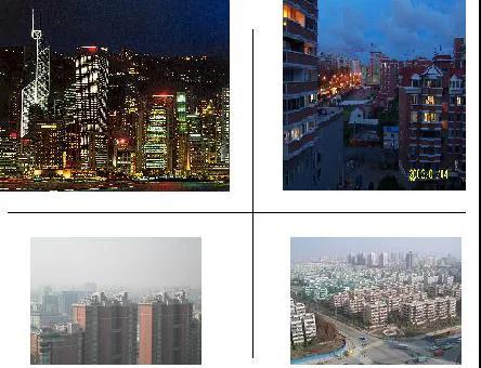
Characteristics of the application environment: Base stations are densely distributed, requiring a small coverage area of a single base station. It is hoped to minimize cross-area coverage, reduce interference between base stations, and increase download rates.
Antenna selection principles:
Polarization mode selection: Due to the difficulty in selecting base station sites in urban areas and limited antenna installation space, it is recommended to use dual-polarization antennas and broadband antennas;
Direction pattern selection: In urban areas, the main consideration is to improve frequency reuse, so directional antennas are generally used;
Selection of half-power beam width: In order to better control the coverage of the cell to suppress interference, the horizontal half-power beam width of the urban antenna is selected to be 60~65°;
Selection of antenna gain: Since base stations in urban areas generally do not require a wide range of coverage, it is recommended to use a medium-gain antenna. It is recommended to use an antenna with a gain of 15-18dBi in urban areas. If the microcell antenna is used to fill blind spots in urban areas, a lower antenna can be selected;
Downtilt angle selection: Since the antenna tilt angle in urban areas is adjusted relatively frequently, and some antennas need to be set to a larger tilt angle, and mechanical downtilt is not conducive to interference control, it is recommended to use a preset downtilt angle antenna. You can choose an antenna with a fixed electrical downtilt angle, or an electrically adjustable antenna when conditions are met.
3.2 Antenna selection for suburban rural base stations

Application environment characteristics: base stations are sparsely distributed, the business volume is small, the data service requirements are relatively low, and wide coverage is required. In some places, there is only one base station around, so coverage becomes the most important concern. At this time, the antenna selection should be considered based on the area that needs to be covered around the base station.
Antenna selection principles:
Direction pattern selection: If the base station is required to cover the surrounding area, and there is no obvious directionality, and the traffic distribution around the base station is relatively scattered, it is recommended to use omnidirectional base station coverage. At the same time, it should be noted that due to the small gain of omnidirectional base stations, the coverage distance is not as far as that of directional base stations. At the same time, when installing omnidirectional antennas, pay attention to the impact of the tower on coverage, and the antenna must be kept perpendicular to the ground plane. If the local authority has longer coverage requirements for base station coverage, directional antennas need to be used to achieve this. In general, directional antennas with half-power beamwidths of 90°, 105°, and 120° in the horizontal plane should be used;
Selection of antenna gain: Select the antenna gain according to the coverage requirements. It is recommended to choose a higher gain (16-18dBi) directional antenna or a 9-11dBi omnidirectional antenna in suburban and rural areas;
Selection of downtilt method: In suburban and rural areas, there are not many adjustments to the downtilt of the antenna, and the adjustment range and characteristics of the downtilt angle are not high. It is recommended to use a mechanical downtilt antenna. At the same time, when the antenna is hung above 50 meters and there are near-end coverage requirements, zero-point filling antennas can be given priority to avoid the blackout problem under the tower.
3.3 Highway coverage base station antenna selection
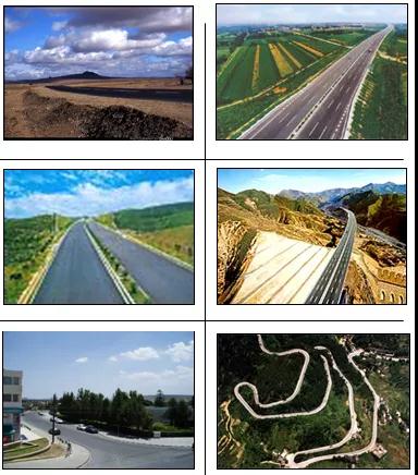
Application environment characteristics:In this environment, the business volume is low and users move at high speed. At this time, the focus is on solving the coverage problem. Generally speaking, what it wants to achieve is strip coverage, so two-way cells are mostly used for highway coverage; omni-directional cells are also used in areas passing through towns and tourist spots; then, wide coverage is emphasized, and the type of antenna to be used must be determined based on the choice of site and site type. Different highway environments vary greatly. Generally speaking, there are relatively straight highways, such as highways, railways, national highways, provincial highways, etc. It is recommended to build a station next to the highway, using S1/1/1 or S1/1 station type, with high-gain directional antennas to achieve coverage. There are winding and undulating roads such as winding mountain roads, self-built mountain roads at the county level, etc. It must be combined with rural coverage near the highway and choose a high place to build the station.
When selecting an antenna during initial planning, try to choose a high-gain antenna with a wide coverage distance for wide coverage.
Antenna selection principles:
Directional pattern selection: In base stations that aim to cover railways and highways, narrow-beam, high-gain directional antennas can be used. The antenna form can be flexibly selected according to factors such as local terrain undulations and turns at the deployment site;
Selection of antenna gain, the directional antenna gain can be selected from 17dBi-22dBi, and the omnidirectional antenna gain can be selected from 11dBi;
Selection of downtilt method: Highway coverage generally does not have a downtilt angle. It is recommended to use a cheaper mechanical downtilt antenna. When the distance is more than 50 meters and there are near-end coverage requirements, antennas with zero point filling (greater than 15%) can be given priority to solve the problem of black spots under the tower;
Front-to-back ratio: Since most users of highway coverage are fast-moving users, to ensure normal handover, the front-to-back ratio of the directional antenna should not be too high.
3.4 Base station antenna selection for mountain coverage

Application environment characteristics:In remote hilly and mountainous areas, mountains block the airwaves severely, resulting in radio wave propagation attenuation, making coverage difficult. It usually has wide coverage, with scattered users distributed within a wide coverage radius of the base station, and the business volume is small. The base station may be built on the top of the mountain, on the mountainside, at the foot of the mountain, or at a suitable location in the mountainous area. It is necessary to distinguish different user distribution and terrain characteristics to select base station locations, models, and antennas. The following situations are relatively common: building a website in a basin-type mountainous area, building a website on a high mountain, building a website halfway up a mountain, building a website in an ordinary mountainous area, etc.
Antenna selection principles:
Selection of directional pattern: The choice of directional pattern depends on the location, station type and surrounding coverage requirements of the base station. You can choose an omnidirectional antenna or a directional antenna. For base stations built on mountains, if the location to be covered is relatively low, a pattern with a larger vertical half-power angle should be selected to better meet vertical coverage requirements;
Antenna gain selection: Choose medium antenna gain, omnidirectional antenna (9-11dBi), directional antenna (15-18dBi) depending on the distance of the area required to be covered;
Inclination angle selection: When building a station on a mountain and the area to be covered is at the bottom of the mountain, an antenna with zero point filling or a preset downtilt angle should be selected. The size of the preset downtilt angle should be selected based on the relative height of the base station and the area to be covered. The larger the relative height, the larger the preset downtilt angle should be.
3.5 LTESummary of base station antenna application scenarios
Based on the above choices and combined with the special conditions of LTE, the recommended antenna selection principles are:
Table 3-1 Summary of antenna application scenarios
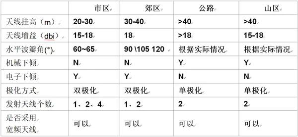
Generally, LTE site selection uses existing facilities, so whether there is enough space to install LTE antennas and whether the height meets the LTE plan are the biggest problems. Therefore, the actual project adopts technical parameters such as which polarization method, whether to use a wide-band antenna, and the downtilt angle method. It is necessary to conduct a detailed survey of the existing facilities and make a reasonable plan based on the actual situation. Due to the presence of MIMO technology in LTE, 2T2R and 4T4R are currently commonly used. Taking into account factors such as website construction costs, for 2T2R situations, dual-polarized antennas are generally used; for 4T4R situations, two dual-polarized antennas are generally used, and the distance between the antennas is 1-2λ, which corresponds to about 30-50cm for 2.6G.
4 5G Massive MIMO AAUand application scenarios
The main content of this section briefly describes the antenna and application scenario selection of 5G AAU.
4.1 5G Massive MIMO AAU
Multiple input and output technology (MIMO), which has been very mature in the 4G era, can effectively utilize multiple spatial channels existing between multiple antennas between the transceiver and transceiver systems to transmit multiple mutually orthogonal data streams, thereby improving data throughput and communication stability without increasing communication bandwidth.
The Massive MIMO technology developed from 4G to the 5G era is an upgraded version of MIMO technology. Based on limited time and frequency resources, hundreds of antenna units are used to serve up to dozens of mobile terminals at the same time, further improving data throughput and energy usage efficiency. The 5G communication frequency is high and the antenna size is shortened, allowing more antennas to be packed in the original space. Massive MIMO technology has set the tone for communication technology in the 5G era. Therefore, antennas have become another explosive growth component after the radio frequency front-end in the 5G era. Base station antennas account for 20%, and terminal antennas account for 80%.
Due to the extensive use of Massive MIMO technology in 5G base stations, the internally integrated antenna uses a large number of oscillators and also integrates transceiver units, so it is also called an active antenna array unit (AAU). Its internal structure schematic diagram and product form are shown in the figure below.
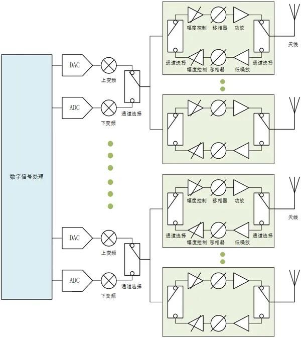
Figure 4-1 Massive MIMO AAU structural schematic diagram
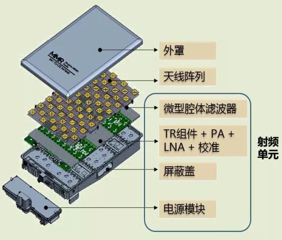
Figure 4-2 Exploded view of Massive MIMO AAU product form
For AAU in the <6GHz frequency band, communication equipment manufacturers generally use 192 oscillators. There are 12 rows in the horizontal direction and 8 columns of oscillators in the vertical direction. Plus 45° dual polarization, there are a total of 12x8x2=192 oscillators. Each group of three oscillators is called an antenna, so the AAU has a total of 192/3=64 antennas. If every 6 oscillators form an antenna, the AAU has 192/6=32 antennas.
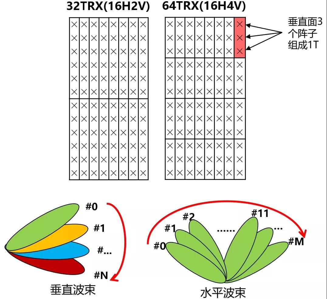
Figure 4-3 65TR and 32TR AAU antenna element diagram
AAUs in the <6GHz band usually use all-digital beamforming. It can be considered that the number of antennas, the number of transmission channels, and the number of power amplifiers are the same. The number of antennas is an important factor in coverage. The more the number of elements, the narrower the beam and the more concentrated the energy. The more antennas and channels, the more power amplifiers inside the AAU, the greater the consumption of baseband resources, and the higher the cost of the equipment.
4.2 5GSignal fading model
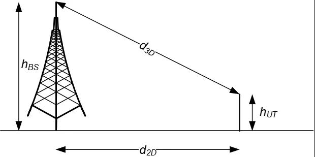
3GPP TR 38.901 provides four scenarios: indoor hotspot office area (InH-Office), urban micro-cell street (UMi-Street Canyon), urban macro cell (Uma), and rural macro cell (RMa). Each type of scenario is divided into non-line-of-sight (NLOS) and line-of-sight (LOS) scenarios, with a total of eight propagation models. This article selects the path loss model in the urban macro station Uma-LOS/NLOS scenario. where fcOperating frequency (GHz), hBSEffective height of base station antenna (m), hUTEffective height of mobile station antenna (m), d2DHorizontal distance between base station and mobile station (m), d3DThe straight-line distance between the base station antenna and the mobile station antenna (m).
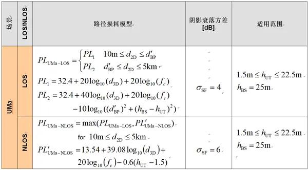
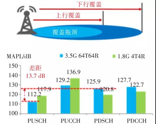
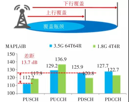
According to the above table, the typical maximum allowable path loss (MAPL) of different channels of urban macro stations can be calculated according to the following formula. It can be seen that the maximum allowable path loss gap between the uplink and downlink of 5G NR 3.5GHz reaches 13.65 dB, the network coverage is limited in the uplink, and is limited by the uplink PUSCH channel.
PLmax=PTx-Lf+GTx-Mf-Ml+GRx-Lp-Lb-SR
where PTxBase station transmit power, LfFeeder loss, GTxBase station antenna gain, MfShadow fading and fast fading margin, MlInterference margin, GRxCell phone antenna gain, LpBuilding penetration loss, LbBody wear and tear, SRxCell phone reception sensitivity
4.3 5G AAUApplication scenarios
In dense urban areas, the complex wireless environment leads to worsened interference, and high-rise buildings lead to high vertical coverage requirements and high user capacity requirements. 64TR equipment can provide better massive MIMO beamforming, achieve high-traffic multi-user MIMO transmission, and significantly improve vertical dimension coverage. In suburbs and rural areas, the MU-MIMO pairing success rate decreases and 64TR equipment cannot fully utilize its capacity advantages, so low-configuration equipment can be used. Using 32 antennas can meet the needs. For more remote areas, the capacity requirements are not high and the main problem is to solve the coverage problem. At this time, even Massive MIMO is not needed. Just use the 8-port RRU to connect the antenna.
The figure below shows a scenario-based network coverage solution proposed by an equipment manufacturer. Macro site is the most important product form. The 64TR AAU solves the continuous high capacity demand in the 4G/5G stage, and the low-configuration 32TR AAU solves the low-cost network construction demand in 4G/5G low-traffic areas. Indoor distribution system products include 2TR and 4TR equipment, which use passive indoor distribution systems on the existing network or new construction to solve high-value, high-traffic indoor scenarios. In addition, micro station base station 4TR radio frequency unit (RRU) products are widely used in busy and heating scenarios such as residential areas and pedestrian streets.
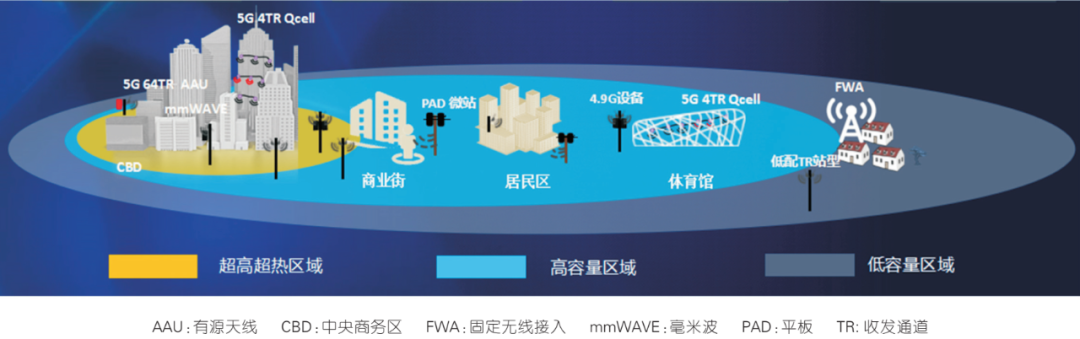
Figure 4-4 A scenario-based network coverage solution from an equipment manufacturer
It can be seen from the calculation results in Section 4.2 that the 3.5 GHz band 5G NR uplink coverage is limited, mainly due to limited terminal power. Considering that the uplink and downlink service rate requirements will still be asymmetric in the future after the launch of 5G (the downlink rate requirements are much higher than the uplink), in order to keep the existing network structure unchanged and reduce network construction costs, so that operators can quickly superimpose and deploy 5G on 4G live sites, uplink and downlink decoupling (SUL) can be used to solve the problem of uplink coverage bottlenecks. That is, old LTE equipment is used in the uplink, part of the 1.8 GHz FDD bandwidth is re-cultivated for 5G NR to improve coverage, and 5G NR is deployed in the 3.5 GHz band in the downlink.
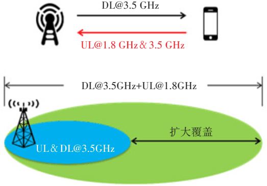
Figure 4-5 Decoupling solution using different frequency bands for uplink and downlink
This article is reproduced from “ Microwave Radio Frequency Network ", support the protection of intellectual property rights, please indicate the original source and author when reprinting. If there is any infringement, please contact us to delete it.
Related Recommendations