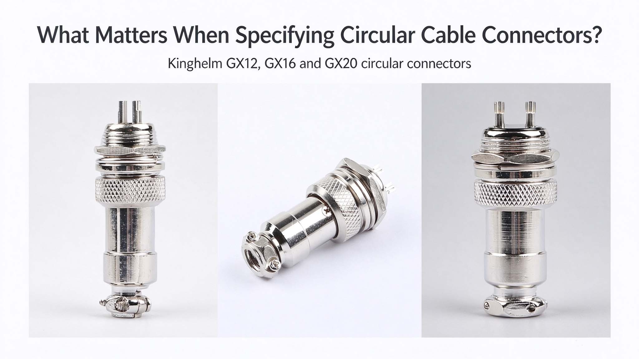
A circular cable connector provides a detachable electrical connection between a cable and a piece of equipment, or between two cable assemblies. Its main components typically include an outer shell, an insulating insert, metal contacts and a coupling mechanism, which may be threaded or push-pull.
Two circular connectors with the same pin count may still differ in contact arrangement, thread or coupling style, electrical ratings and installation dimensions.
Kinghelm's GX series covers GX12, GX16 and GX20 models in a range of shell sizes and pin configurations. Because dimensions and ratings change from one model to the next, use the technical drawing as the reference for the equipment interface, cable termination and available installation space.
What Should You Know Before Choosing a Circular Connector?
The outer shell protects the internal components and provides mechanical support. Inside, the insulating insert holds the contacts in position and keeps them electrically separated. Metal contacts carry power or signals, while the coupling mechanism secures the two mating halves.
Circular connectors are common in industrial controls, sensors, instrumentation and communication equipment. For those installations, circuit count, mounting space and electrical demand matter alongside the connector's mechanical construction.
Pin Count, Connector Size and Electrical Requirements
Pin Count
Start by listing the required power, signal and return connections, then compare them with the available contact positions. A 2-pin connector may suit a basic two-conductor circuit, while additional contacts can accommodate other signals or connections. A higher pin count may also require a larger shell or leave less room for individual conductors. Check the pin assignment against the equipment design rather than selecting by pin count alone.
Connector Size
GX12, GX16 and GX20 are series names, not proof of the thread diameter. The product pages currently list M12, M16 and M20 socket specifications, but only the technical drawing establishes the thread callout, panel-hole size, coupling clearance and wiring room.
For KH-GX20-2P, pay particular attention to the thread callout and mounting dimensions before preparing the panel opening. The KH-GX12-4P carries an M12 specification, but that alone does not make it interchangeable with an IEC-standard M12 sensor connector; compare the thread, contact arrangement and coupling before choosing a replacement.
The KH-GX12-4P drawing treats the panel mounting detail and cable-nut thread separately. Check the panel cutout, coupling-ring clearance and rear cable entry together when planning the installation.
GX20 can be too large for a compact enclosure, while GX12 still needs clearance for the coupling ring and cable bend. Use the complete connector envelope, not the family number, to judge the installation.
The KH-GX12-4P technical drawing gives 15.0 mm from the mounting face to the rear on the male connector, 15.5 mm on the female and 33.5 mm overall for the male. It also shows a recommended mounting hole measuring 11.20 mm by 12.00 mm. These figures matter when the connector sits behind a panel or next to other hardware.
Electrical Ratings
Rated voltage, current and operating-temperature range are specific to each model. A series catalogue can hide changes that follow pin count even when the outer shell stays the same.
In the GX12 datasheet, the 2-pin version is rated at 200 V AC RMS, while 3-pin through 7-pin versions are rated at 125 V AC RMS. Kinghelm currently lists 2P through 6P, so a 7P variant requires separate confirmation. Current is 5 A across those configurations; the KH-GX12-4P product page also lists 125 V and 5 A. These figures belong to GX12, not the wider GX series.
Other values on the datasheet include a dielectric withstand voltage of 1500 V AC for 1 minute, insulation resistance of at least 2000 MΩ and contact resistance no greater than 5 mΩ. For continuous operation, assess the rated current alongside conductor size, ambient temperature and heat dissipation; these electrical test values should not be treated as operating ratings. The KH-GX12-4P product page also lists an operating temperature range of -20°C to +85°C; this is not the same as a temperature rise caused by current.
Mating Compatibility and Cable Connection Requirements
The mating interface and rear cable assembly often determine whether a connector can be installed even after its ratings fit. Contact layout, coupling style, termination and bend space need to be considered together.
Male and Female Matching
Male versions usually have projecting pins, while female versions use socket contacts. Their contact positions and coupling mechanisms must match the equipment interface.
Kinghelm supplies KH-GX12-4P as a male and female set. The drawing shows threaded coupling, a Bakelite insulating insert and four numbered positions. Because male and female dimensions differ, order the two halves as the intended mating pair rather than combining them from separate models.
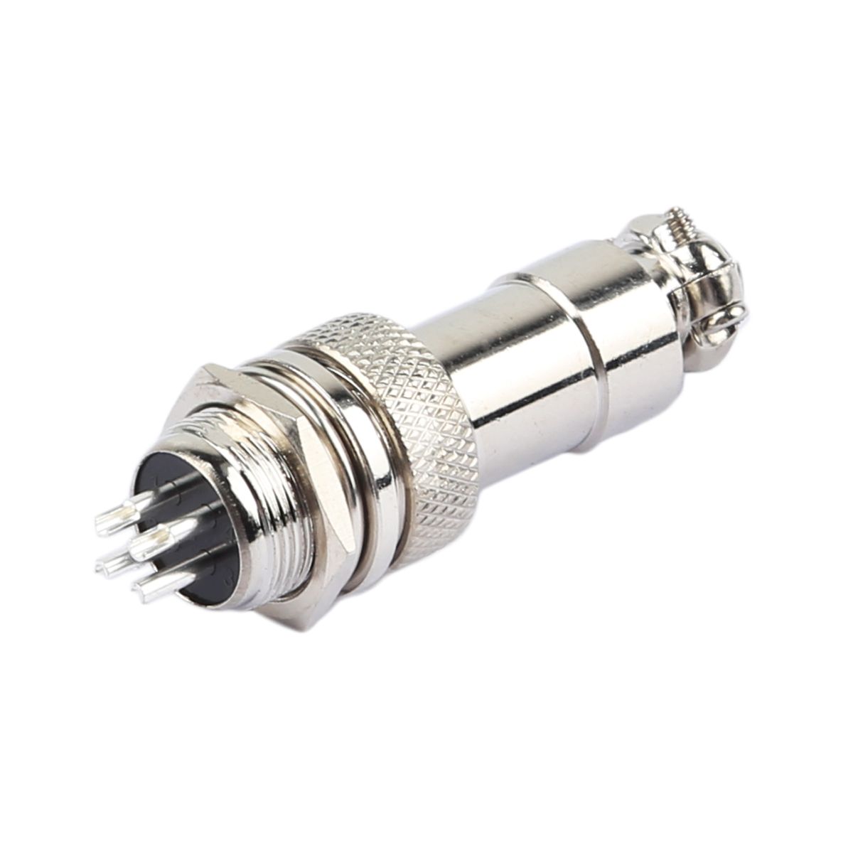
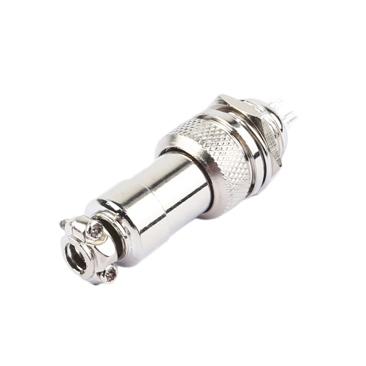
The KH-GX12-4P drawing specifies a zinc-alloy female shell, a brass male shell and copper contacts with silver and nickel plating. Similar-looking products from another source should not be assumed compatible. Specify the full Kinghelm model, required half and current drawing revision.
Cable Connection and Installation
KH-GX12-4P uses solder termination. Its technical drawing specifies a Ø0.8 mm solder-cup opening and a Ø1.2 mm inner diameter for the solder cup. These dimensions are specific to this model and should not be applied to GX16 or GX20.
Jacket diameter, conductor stranding, bend radius and strain relief also affect assembly. Check that the cable diameter and bend radius fit the rear hardware, and that the jacket is not pinched or the solder joints placed under strain. The GX12 datasheet specifies 500 mating cycles, a figure that should not be assumed for other GX models.
Kinghelm GX Series: Product Options for Different Requirements
Kinghelm's GX12, GX16 and GX20 ranges differ in shell size, pin count, configuration and ratings. Pin count also does not predict current capacity. KH-GX16-2P and KH-GX20-2P are both two-pin sets, but their published voltage and current ratings differ.
| Model | Connector Series | Pin Count | Configuration | Rated Voltage | Rated Current |
|---|---|---|---|---|---|
| KH-GX12-4P |
GX12 | 4 | Male and female set | 125 V | 5 A |
| KH-GX16-2P |
GX16 | 2 | Male and female set | 220 V | 7 A |
| KH-GX20-2P |
GX20 | 2 | Male and female set | 250 V | 15 A |
Refer to the linked product pages and datasheets for the specifications of each model and configuration.
An IP or environmental rating should also be confirmed separately; a metal shell alone does not establish ingress protection. Kinghelm can review pin assignment, male or female configuration, cable construction and installation environment against a specific model.
Conclusion
A pin count and series name are only starting points. The mating interface, termination, dimensions and electrical ratings all have to fit the equipment and cable assembly, and the technical drawing and datasheet for the exact model remain the working references.
For a Kinghelm GX12, GX16 or GX20 connector, provide the required pin count, male or female configuration, cable specifications, working voltage and current, and installation conditions. Kinghelm can review those requirements and provide the corresponding technical documentation. Contact Kinghelm