






















Service Hotline
Tech Applications

Tech Applications
Connector Selection Checklist: Matching RF, Board-to-Board and Wire-to-Board Families to Your Design
2026-09-17
1717
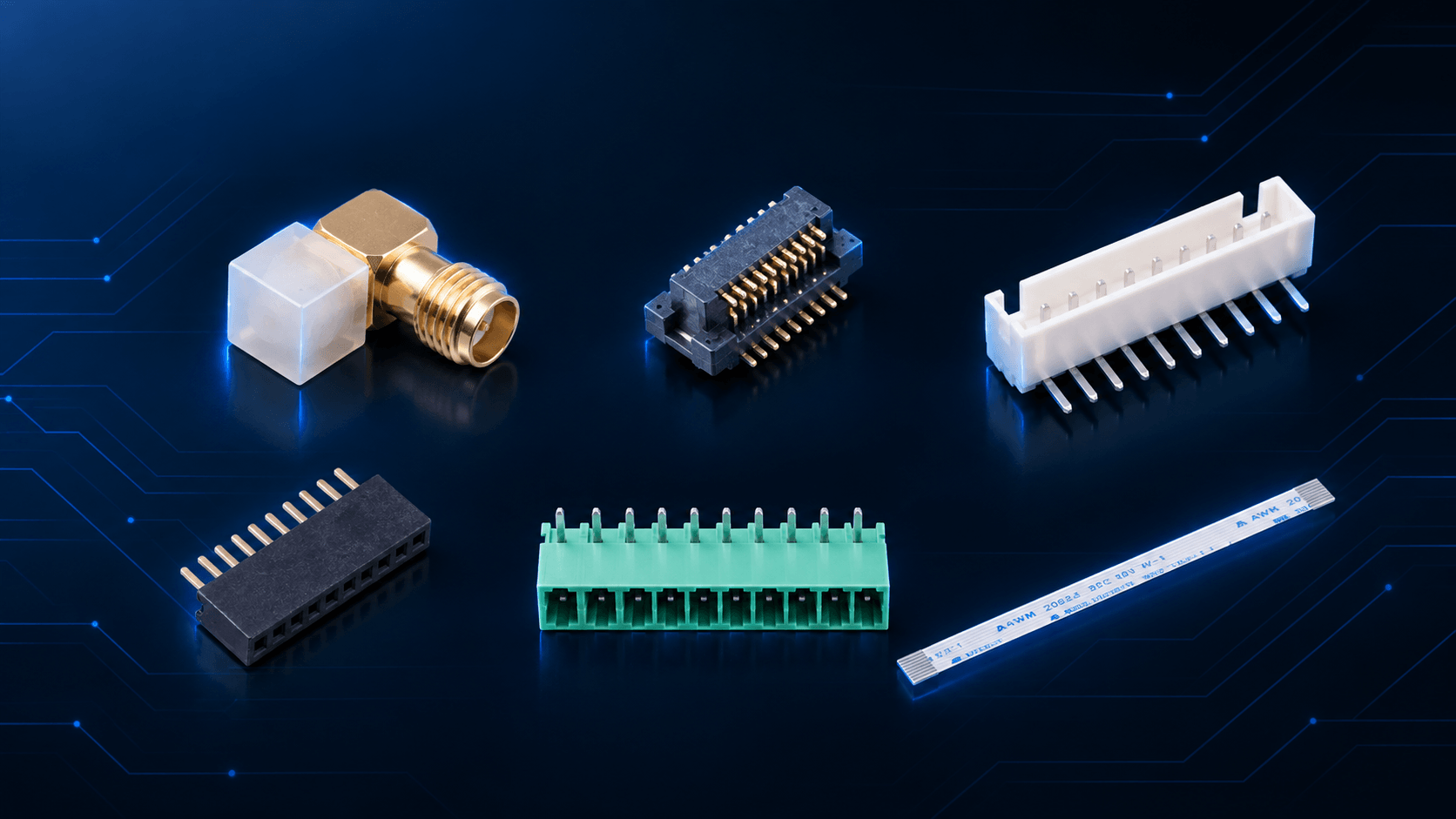
Most of the work in how to choose a connector for PCB design is finished before anyone opens a connector catalogue, which is why a connector selection checklist starts with the design rather than with a part number. Three things are usually already settled by the time the layout is frozen: the impedance and frequency the RF path has to carry, the stack height and board outline the enclosure allows, and whether anyone will need to open the unit after it ships.
Treat those three as inputs rather than options. A 50 Ω path running from DC to 6 GHz points at coaxial interfaces and quietly removes ribbon, header and terminal-block families from the shortlist, whatever their unit price looks like. A 1.2 mm gap between two parallel boards is not a preference; it decides which board-to-board pitches stay realistic. If the assembly has to be serviced in the field, a permanently soldered board-to-board pair drops out long before cost is discussed.
Keeping those answers in one place is what makes the checklist worth reusing. It records what the design has already decided, which leaves a candidate list small enough to compare properly.
Connector Selection Criteria That Eliminate Families, In Order
Once those inputs are fixed, connector selection criteria narrow the field in sequence. Running the three questions below out of order is what creates the awkward cases: a part that meets the electrical requirement, cannot be written into a purchase order cleanly, and arrives with drawings that disagree with the footprint.
Signal, power, or both.
The first question is what actually travels through the contact. Signal-only paths with controlled impedance lead toward coaxial families; power-only paths lead toward terminal blocks and heavier headers; mixed paths usually force a compromise on pin count or plating. This single answer typically removes half the candidates.
Board-to-board, or board-to-cable.
A connection that stays fixed between two boards for the life of the product belongs to the board-to-board and FFC/FPC families. One that has to route around a hinge, pass through a chassis wall, or unplug for service belongs to wire-to-board or cable-assembly territory. Leaving this question until late is expensive, because a design that assumes a pluggable harness but specifies a soldered joint is reworked on the production line rather than on paper.
Current, and how often it is mated.
Current sets the minimum contact size and, indirectly, the pitch. Mating frequency sets the contact geometry. A connector mated once during assembly and one mated every time a technician swaps a module are different products, even when they share a 1.27 mm pitch and the same footprint.
The order matters because each answer narrows the next one. Choosing pitch first and working backwards to current is how a 0.5 mm part ends up specified for a load it cannot carry.
What Survives: Connector Selection By Application
After those three questions, what usually remains is one family, occasionally two. The table below is the comparison sheet worth carrying into connector selection by application. The last column is the item to have in writing before an order is raised.
| Family | Typical pitch / interface | Current | Typical mating life | Confirm before ordering |
|---|---|---|---|---|
| RF / coaxial | 50 Ω interface (SMA, SMB, IPEX, FAKRA), DC to 6 GHz | Signal path, up to 1 A | ~500 cycles (typical) | Impedance, upper frequency and contact plating. KH-SMA-K513-G |
| Board-to-board | 0.5 mm (2.5 mm XH also counted here) | ~0.5 A per contact | ~20 to 30 cycles (typical) | Stack height and alignment tolerance. KH-WB105-F20E-04L, KH-XH-11A-Z |
| Wire-to-board | 2.54 mm | 3 A / 250 V | ~30 cycles (typical) | Wire gauge and lock retention. KH-A2504-10AW |
| FFC / FPC | 0.5 mm / 1.0 mm | ~0.5 A per contact | ~20 to 30 cycles (typical) | Insertion direction and bend radius. KH-FFC-A0.5-10P, KH-FFC-V0.5-10P |
| Pin and female header | 1.27 mm (2.0 / 2.54 mm in the same family) | 1.0 A / AC 500 V | ~50 cycles (typical) | Stack height and selective gold plating. KH-1.27FH-1X10P-H4.3 |
| Terminal block / industrial | 3.81 mm | 8 A / 300 V, AC 2000 V/min | ~50 cycles (typical) | Creepage distance and terminal torque. KH-15EDGRC-3.81-10PG |
Pitch, current, withstand voltage, temperature range, and contact and insulation resistance figures above come from published Kinghelm datasheets. Mating life is an industry-typical reference range rather than a guaranteed specification, and is worth confirming per part number.
The Connector Selection Checklist Before Samples or a PO Go Out
A shortlist is not an order. The connector selection checklist below is what a purchasing file should be able to answer from supplier documents rather than from a conversation, so that incoming inspection has something to check against.
| Check | Evidence worth filing |
|---|---|
| Pitch, position count and land pattern | Datasheet drawing plus a 3D or footprint file matched against your layout |
| Stack height and alignment tolerance | Dimensional drawing with tolerances, and a mated sample pair where the stack is critical |
| Current derating | Contact current rating at your operating ambient, not at 25 °C |
| Contact resistance, insulation resistance, withstand voltage | Rated values from the datasheet or a test report |
| Plating and contact material | Plating thickness and base metal stated in writing |
| Operating temperature and reflow profile | Rated range plus the recommended reflow curve |
| Mating life and keying | Rated cycles and the anti-mis-mating feature for your position count |
| Retention and vibration | Insertion and withdrawal force, plus any latch or lock detail |
| RoHS and REACH | A current declaration rather than a general statement |
| Sample and batch consistency | A sample from the production process, and the incoming inspection criteria |
If Board-to-Board Is What Survived
Board-to-board deserves one extra step, because it is the family where the electrical and mechanical answers are decided together. The number that causes most late changes is not pitch. It is stack height tolerance. A 0.5 mm connector designed for a fixed 0.9 mm stack will not absorb 0.3 mm of accumulated PCB thickness and solder-mask variation across a panel. Alignment follows the same rule: at 20 to 40 positions on 0.5 mm pitch, a fraction of a millimetre of misalignment is enough to bend contacts on the first insertion.
If board-to-board is what survived your shortlist, the guide on how to choose the right board-to-board connector covers stack height, coplanar and right-angle options in more detail.
If a shortlist needs a second opinion before the layout is frozen, our engineers will review stack height, current derating and mating life against your drawing. Samples for any of the families above can be requested through the sample application page, and technical questions reach us fastest through the contact form.
Related Recommendations